A flange is a flat pipe connection with round or square holes for fasteners (bolts, studs, etc.). These components are used to create a highly durable and leak-proof joint over a long pipeline section.
Flanged connections for steel pipes are a very common method. They feature evenly spaced holes for studs and bolts.
Flanged connections are not very common in domestic systems. This type of technology is designed for industrial applications. If a steel flanged unit needs to be installed, special attention must be paid to all markings according to the relevant standards.
Flanged joints have become the most popular type of detachable steel connectors in the chemical, industrial, and housing and utilities sectors. This is due to their leak-proof design, simple construction, and ease of manufacture and installation.
What is a flange and how does it work?
The term "flange" encompasses not only a plumbing fixture but also a method of fastening pipes, which is used in practice across all industrial sectors. Flanged connections of steel pipes are characterized by their tightness and durability.

Moreover, the connection is detachable. This means that after removal, all necessary repairs can be carried out and the pipeline section can be reused. Flange connections for steel pipes are selected based on the intended purpose of the network, and various flange types made from different materials are used.
With a wide variety of steel options, the following main types of structures are distinguished:
- Pass-through options. These are successfully used to extend pipeline lengths.
- Blank flanges. This is a dead-end version of these parts.
It turns out that flanges are connecting parts that are installed in long-term networks and in pipelines with high internal pressure, but monolithic connections by welding are considered a higher priority.
Flow through the pipeline is stopped before installation and restarted only after all work has completely ceased. Particular attention is paid to pressure; it is recommended to gradually increase the load on this component.
Application areas of connecting parts
When discussing such an element, it's important to clarify that it's not a fastening component. The main purpose of this device is to create a support structure for the fastening bolts while simultaneously ensuring a tight seal.

As a shut-off or connecting component, they are used in utility networks in the housing and communal services sector and in the oil production industry. They are also widely installed in the fuel and gas industries. In these industries, extremely durable and long-lasting flange connections are used for installing measuring instruments into the network.
Various manufacturing technologies and types of materials for these elements enable the efficient operation of networks that transport aggressive substances under high pressure.
When laying steel pipe systems, discs made of similar materials are most often used. This creates a uniform level of load pressure and serves as a safeguard against damage to components due to temperature fluctuations.
Such damage is typical for seams on materials with different thermal conductivities. Cast iron, aluminum, brass, and bronze flanges are used on steel pipes. However, carbon steel products are the undisputed leader among options for this type of work. There are several reasons for this:
- Not a high cost.
- Practicality.
- Easy to process.

Flanged connections are found in every industry. The wide variety of materials used to manufacture these devices allows for the efficient use of any pipeline.
Some types of systems require a special recess for gaskets. Flange connections in gas transmission networks require particularly careful inspection. These require flanges that have undergone detailed quality testing.
Features and specifications
The main characteristic of flange fasteners is their design features. In Russia and the CIS, the most popular standards are:
- GOST 12820-80 defines the design features of flat-type welded flanges.
- GOST 12821-80. It defines the design characteristics of butt-welded flanges.
- GOST 12822-80. This document defines the design characteristics of steel flanges mounted on a welded disc.
The devices that fall into these three main groups are designed for direct connection between the network and equipment. The installation conditions for each of the presented mechanisms vary.
Flat welded steel partsDuring installation, such an element is "slid" onto the pipe, and then welded around it with a couple of welds.

Butt welded steel mechanismThe installation of this steel part, compared to the first option, requires only one weld—the connection.
This process joins the end of the pipe and the "collar" of the coupling mechanism end-to-end. This significantly simplifies the fastening process and reduces installation time.

Free-standing steel structure on a welded ringIt includes a main part and a ring, and they, in turn, must have the same nominal volume and pressure.

If we draw a parallel with the previously mentioned options, then in this mechanism the ease of installation is at a higher level, because the disk itself is welded to the pipes, and the flange is left in a free position.
This allows connecting bolt holes on free-standing components and similar mechanisms on fittings to be performed without difficulty, even in difficult-to-reach areas. Rotating the pipe is also not required for this connection.
The positive aspects of their use include the fact that when selecting a stainless steel pipe, you can install a stainless steel ring and a flange structure made of carbon steel.
Other classifications are also used around the world, for example:
- DIN are German standard norms, they are valid in European countries;
- ANSI/ASME are American standard codes and are used in Japan, the USA and Australia.
These standards are translated into special tables, where there is a clear indication of which standard defines the characteristics of a particular product.
Designs of flange sealing surfaces
 As previously mentioned, these steel pipe fittings are manufactured in accordance with GOST standards. These fittings are manufactured with sealing surfaces in the following designs:
- The plane is designated as A.
- Depression. Designated as F.
- Groove. Its designation is D and M.
- For lens gaskets. This option is designated as K.
- Protrusion for connection. Designated B.
- A projection. It is designated as E.
- Spike. This type is designated by C and
- For oval-section gaskets. This type is designated J.
Valve flanges must be produced with sealing surfaces of types A, B, D, F, J, K, M. Other options for valve flange sealing surfaces are permitted only at the customer’s request.
Flanges with sealing surfaces A, B, C, D, E, F are used with joints that are sealed with the following gaskets:
- jagged;
- metal;
- graphite;
- metallographite.
Flanges are manufactured in accordance with requirements that ensure the maintenance of geometric dimensions and mechanical characteristics.
For example, flat flanges can be produced by welding, provided that weld conditions are met during operation. This must be achieved along the entire length of the cross-section on the device. Ultrasonic testing is recommended for the quality of such welds.
As a rule, the manufacturing method is determined by the manufacturer, unless the customer has additionally discussed this when placing an order.
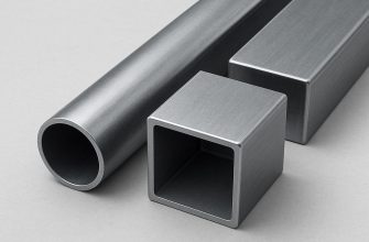
Round and square types
According to the types of construction, the data characterize:
- The nominal bore size is measured in millimeters and designated as DU.
- The magnitude of nominal pressure. It is measured in kgf/cm2.
- Material used as raw material.
- Direct execution. In this situation, numbers from one to nine are used; they indicate the required type of surface to be installed under the gasket.
The technological characteristics of steel flange connections on pipes are directly related to the technological processes and the workpieces used for the work.
 Flanges come in round and square shapes, depending on the manufacturing method. Currently, the number of fittings for pipelines requiring square shapes is limited. However, despite this, such fittings remain relevant.
For these reasons, for pressure values that do not exceed 40 kgf/cm2 in relation to GOST 12815-80, not only round-shaped mechanisms are provided, but also square-shaped types.
The pressure they can withstand
 This is a very significant indicator of the mechanism's performance. The values for these parameters depend on the product's geometric dimensions. The type of sealing surface also influences this.
Welded flat steel products (GOST 12820-80) and free-standing steel parts on a welded disk (GOST 12822-80) can withstand loads of up to 25 kgf/cm². Butt-welded versions (GOST 12821-80) can withstand loads of up to 200 kgf/cm².
In such situations, the quantity is shown in various representations, these are:
- Pa;
- MPa;
- atm;
- kgf/cm2 and others.
But, when releasing products of this line, the main measuring parameter is kgf/cm2.
Installation Features
The key to installing a flanged fastener is tightening its joints. To achieve maximum tightness in a steel structure, only components with high-precision connections should be used.

The further course of work is as follows:
- The surface of the structure is cleaned and degreased.
- Next, the parts are inspected for corrosion, dents, and microcracks. Bolts and nuts should also be carefully inspected. Burrs are removed from the threaded portions. Lubrication of the threaded portions of the bolts and nuts is recommended.
- Next, prepare the gasket. It should be installed precisely in the center, and its correct positioning must be checked. It is not recommended to use old gaskets for this job.
- It's crucial to tighten all the bolts in the correct sequence. First, tighten the first bolt, lightly. Then tighten the bolt on the opposite side. Tighten the third bolt slightly less than the first. Continue tightening the fourth bolt on the opposite side. This sequence is maintained until all the bolts are secure. If you're working with parts that consist of four bolts, a crisscross pattern is used.
Tightening torque requires special attention, otherwise a tight connection cannot be achieved. The tightening torque must be evenly distributed throughout the entire element. During tightening, the bolt is subject to tensile force. Any excessive force can strip the threads or the bolt.
To adjust the tightening force of a flange connection, various techniques are used:
- hydraulic tensioning mechanisms;
- hydraulic torque wrenches;
- pneumatic impact wrenches;
- Hand-operated torque wrenches.
Sometimes, tightening the flange mechanism by hand is used, but this is only feasible for a certain category of people. After securing the flange (within the first 24 hours), the element may lose approximately 10 percent of its tightening force. Additional tightening is recommended 48 hours after installation of the flange mechanism.
Flanging steel pipes is a crucial component. Flanges are selected based on all the characteristics listed above. Technical documentation can provide information on which flanges are best for each specific application.
Video: How to weld a flange to a pipe
After all, pipeline repairs are expensive, especially if a small failure leads to a chain reaction that can lead to a major emergency. To avoid this, it's essential to select flange mechanisms in accordance with regulations and technical documentation.