Installing hydronic underfloor heating, which is becoming increasingly popular, requires many components. One of the most important components is the manifold, whose primary function is to distribute the coolant and control its heating.
We'll examine the design and operation of a manifold, as well as discuss its operating features. We'll also show you how to properly assemble a factory-made manifold for hydronic underfloor heating, as well as a homemade one made from individual parts.
- Operating principle of a manifold for underfloor heating
- Device
- Types of collectors
- Without regulator
- With manual regulator
- With flow meters
- With automatic regulator
- How to assemble a factory manifold model?
- How to make a manifold for underfloor heating yourself?
- Calculation
- Selection of materials
- Assembly
- Features of operation of homemade collectors
- To use or not to use a homemade collector
Operating principle of a manifold for underfloor heating
The manifold is a component of the mixing and distribution unit; without it, the heating system cannot function properly. Its purpose is:
- distribute the coolant;
- control the heating level of the liquid.
The unit's function is to mix the coolant coming from various heating systems with different heating levels (underfloor heating, radiators). After mixing to the required temperature for the hydronic floors, the cooled water is directed into the heating circuits. After passing through the floor line, the cooled water, driven by the pump, moves into the manifold, where it is mixed with the hot water and then returned to the floor.
The flow volumes—hot and cold—are regulated by valves. Temperature sensors monitor the flow.
This principle of action ensures stable and uniform level of heating of rooms.
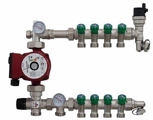
Device
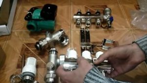
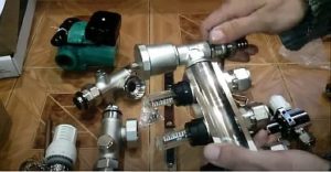
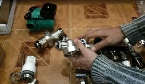
The manifold (comb) consists of two parts—the supply and return units. The core of each part is a large tube with threaded outlets on the side. The number of outlets varies and is selected based on the number of floor circuits.
The main elements of the collector include:
- valves - two or three-way;
- valves - shut-off and balancing;
- temperature sensor;
- pressure gauge;
- pump for ensuring water circulation;
- air vent;
- tees and connectors.
In addition to these components, During the installation of the manifold, a number of other parts will be required.
Types of collectors
Collectors differ in the material they are made of, their characteristics, and also in the methods of adjustment.
Without regulator
The model without regulators is inexpensive. It has no adjustment elements, and water flow distribution is handled by the system's hydraulics.
Experts do not recommend using this design with underfloor heating. Although the device is inexpensive, it is inconvenient to use and can cause malfunction of the entire system.
With manual regulator
This comb model is also inexpensive. Its design is capable of performing its intended function—maintaining the required amount of coolant, at the required heating temperature, for each floor loop.
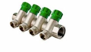
The water temperature is regulated in the mixing unit, and its volume is adjusted manually, only once. From then on, the system will function automatically.
This device is most suitable for underfloor heating that serves as additional heating.
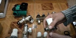
With flow meters
One way to regulate the water flow into the system's loops is to use balancing flow meters. These valves regulate and control the water flow.
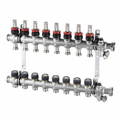
The design consists of a stem with a flange and a graduated window, which allows the water flow rate in each circuit to be determined. Adjustment is made using an adjustment ring located under the cap.
A device with flow meters is the most commonly used type in underfloor heating systems, as it is inexpensive and has proven itself in operation.
With automatic regulator
Automatically regulated manifolds are gaining popularity today. They utilize automatic control elements to manage the coolant flow, using a servo drive for each branch. Working in conjunction with the underfloor heating temperature sensor, this allows for the regulation of the fluid flow into each pipe based on the sensor's temperature readings.
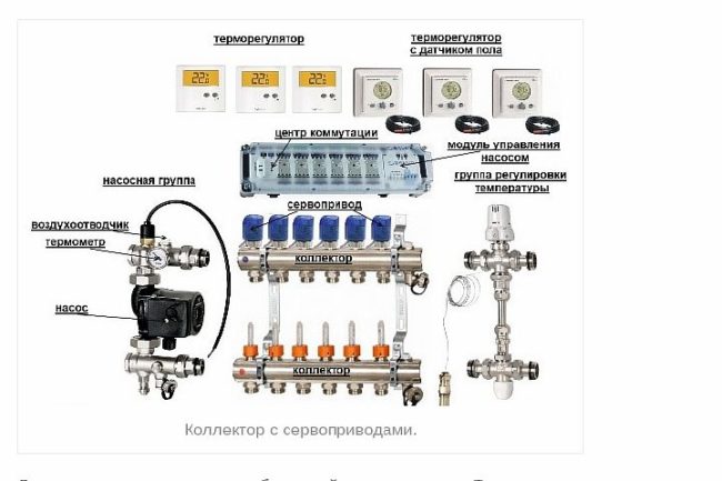
Automatic models are significantly more expensive than simpler models. However, the cost is worth it, as this device makes it easy to maintain a comfortable atmosphere in the home.
When installing such a device, it is important to configure it correctly, otherwise it will not be able to function at full capacity.
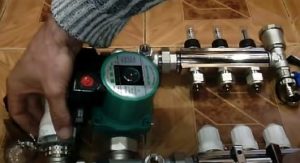
How to assemble a factory manifold model?
When purchasing a manifold, you can choose its components based on your budget and the connection diagram. Factory-assembled models come with the main components pre-assembled, making DIY assembly of the underfloor heating manifold quicker. Once assembled, all that's left to do is connect the connecting hoses.
Before you begin assembling a factory comb, you need to understand what elements it consists of, that is, familiarize yourself with the device, instructions, and assembly drawing.
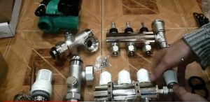
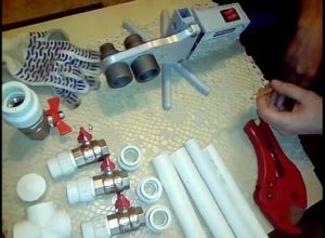
The step-by-step process for assembling a factory-made model of the device yourself is as follows:
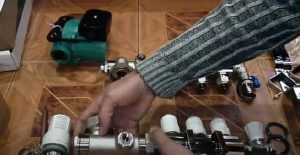
- We unpack the kit, take out and lay out all the parts on the table.

- We determine the distance between fasteners. To do this, we place the fastener against the comb and select the optimal distance for the given structure.
- We fix the limit switch on the feed bar.
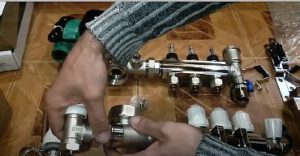
- We take the end valve, wrap tow around its threads—this is one of the connections that needs to be sealed—and screw on the adapter.
- Unscrew the union nut on the faucet and insert it into the right side of the return line. Then, use the union nut to tighten the faucet back into place.
- We take the pump coupling, unscrew the union nut, and screw it into the supply pipe on the left. Then we screw the coupling to the supply structure.
- We do the same manipulations with the second coupling, only we screw it to the return bar.
- We pack a three-quarter valve for the thermostatic head. To do this, we also wrap tow around the threads, and screw the valve into the check valve bar on the left.
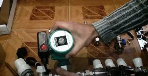
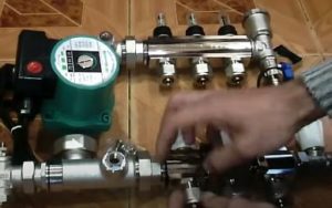
- We connect the circulation pump between the inlet and outlet strips.
- We unscrew the valve head and replace it with a thermal head. We insert the sensor from it into the supply pipe.
- We tighten all connections with a wrench.
- We connect the floor pipes to the finished comb using a Eurocone.
Manifolds are available in steel and with plastic sections. When assembling a plastic part yourself, be careful when tightening the connections.
How to make a manifold for underfloor heating yourself?
Assembling a hydronic underfloor heating manifold yourself is not difficult. However, you should first familiarize yourself with how it works and perform the necessary calculations.
Calculation
Before you start calculating:
- Determine the number of branches of the floor system according to the prepared diagram.
- Determine how many heating devices will also be connected to this unit.
- Determine the adjustment method and control process in the comb.
- Select the installation location of the device - it affects the design features and placement of the pipes.
Afterwards, you can proceed to calculating all system parameters, such as: coolant temperature, water flow rate in all circuits, and determining the location of sections.
In addition, in order for the device to effectively perform its assigned task and not impede the movement of liquid, the following rule must be observed: the distribution manifold must have a diameter with a cross-sectional area that is equal to or greater than S of the cross-sections of all pipes in the main line.
Let's look at an example: if 4 pipes with a diameter of 20 mm are connected to a comb, then the collector cross-section S = 4 (πd²/4) = 4 (3.14 x 20 squared/4) = 1256 mm². That is, the pipe must have a diameter of at least 40 mm.
Selection of materials
To assemble a homemade manifold you will need:
- A comb is a piece of pipe with holes inserted into them for connection to underfloor heating circuits. It is sold ready-made, but can be welded together from metal or polypropylene parts.
- Regulating valves - they are needed for each floor branch and are installed on the supply comb.
- Air vent - it is necessary to release air from the line.
- Brackets are required to attach the device to the wall.
- Drain valve - the coolant will be drained through it.
- Tees and connectors.
You can make your own manifold from these standard parts. In addition to the comb, the underfloor heating distribution unit includes a three- or two-way valve, a pump, and shut-off valves.
Assembly
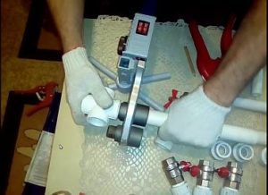
Making a manifold yourself is not difficult. If using polypropylene components, they need to be soldered together to ensure a tight seal.
If the parts are steel, welding skills will be required. Furthermore, the metal manifold requires protection from corrosion, which requires primer or paint.
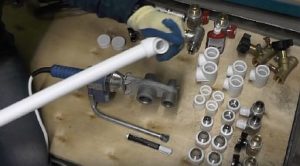
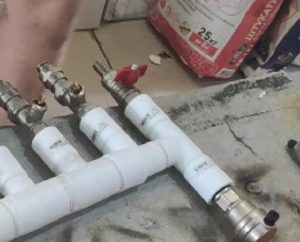
The process of making a polypropylene comb with your own hands:
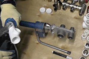
- We weld the feed unit using a 32 mm polyurethane foam pipe and tees of the same diameter. The number of tees depends on the number of floor loops. First, we measure the depth of the pipe insertion into the tee and mark it. Using a soldering iron for polypropylene products, we solder the pipe to the tee.
- We measure the distance from the tee along the pipeline where the pipe enters the tee we measured earlier. We cut the pipe along the marked line and clean the ends.
- We solder a coupling with a tap to the lower outlet of the tee.
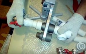
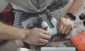
- We repeat the above steps with the second tee. We weld the resulting piece to the first blank. The number of such blanks depends on the number of underfloor heating circuits.
- We solder a tee to one end of the resulting comb, on which we will place an air vent on one end and a ball drain valve on the other.
- We screw on the ball valve and install the air bleeder.
- We make the return manifold using the same principle. However, instead of ball valves, we install regulating valves on the pipes.
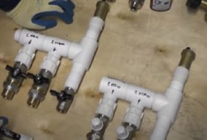
- We fix the prepared combs (feed and return) on the mounting bracket.
All that remains is to secure this underfloor heating unit, connect it to a power source, and connect the circulation pump, which will ensure the movement of the coolant.
Features of operation of homemade collectors
If the manifold is manufactured and connected correctly, its operation is simple, as temperature control, water supply, and distribution within the circuits are automatic. However, as a preventative measure, periodic testing is recommended, which includes:
- checking the operability of all sections of the distribution unit;
- checking the tightness of connections to eliminate possible leaks;
- clarification of the coolant parameters in each loop - the degree of maximum heating, and the time it takes to reach this degree.
It's also important to check whether the temperature meets the specified parameters. To do this, set a specific temperature and periodically read the thermometer readings.
To use or not to use a homemade collector
If you're looking to save money and only need to connect 3-4 floor circuits, it's worth the time to build a polypropylene unit yourself. The key is to reliably seal the soldered joints to prevent leaks.
If you have underfloor heating with a large number of branches, it's recommended to use brass fittings. They're more reliable, but the size of such a comb will be very bulky, but you'll be able to reduce costs.
In summary, a self-assembled manifold, with the right approach, will perform well and can save your family money from major expenses when installing a heating system. Assembly and connection of the manifold assembly must be strictly carried out according to the diagram, and then your water-heated floor will serve you for many years.

Which material is better to use - polypropylene or metal?
Hello. Polypropylene is a more practical material, we recommend using it.