Traditional radiator heating systems were long the only source of heat, but today they are being replaced by underfloor heating. Underfloor heating comes in both electric and hydronic varieties. The key to efficient hydronic heating is the presence of a manifold and its proper installation.
This article will be useful for those planning to install underfloor heating in their home and install the manifold themselves. We'll discuss the different types of this equipment, their design, and installation methods.
- Why do you need a collector?
- Types and operating principles
- Types
- Operating principle
- The design of the collector cabinet
- Pumping and mixing unit
- Collector block
- Correct assembly of a manifold for underfloor heating
- Assembly process
- Installation of a heated floor manifold
- Connecting the transformer substation to the collector
- Collector setup
- Is it possible to install the manifold below the level of the heated floor, for example in the basement?
- Video on how to assemble a manifold yourself
Why do you need a collector?
Essentially, a manifold is a pipe with openings for the inlet and outlet of the coolant; it is also called a distribution and mixing unit. Its function is to maintain the required temperature level in the system and control the water flow.
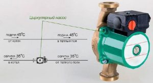
The device is designed to mix water coming from the boiler, where it's heated, with cooled liquid coming from the return line to the required level for underfloor heating. After all, the coolant in the boiler typically heats up to 90 degrees Celsius, which is a high temperature for underfloor heating.
It requires a temperature of 40–45°C, so a manifold is essential. If water flows directly from the heat source into the circuits, it will cause the system to overheat and fail.
Furthermore, the circuits have different lengths and their thermal energy requirements vary. Therefore, a special unit is needed between the boiler and the pipeline to distribute the hot water flow among the circuits.
Types and operating principles
Collector devices vary by the material they are made of—brass, plastic, or stainless steel. They also differ by the valve type:
- With a two-pass design, the coolant is heated continuously. Heated water is supplied continuously, and shutoff valves regulate its volume. As a result, the surface is heated evenly, preventing the system from overheating. However, this model is not suitable for rooms larger than 200 m².
- With a three-way valve—universal equipment, recommended for large spaces. The technology allows for installation with a servo drive (We invite you to learn more about servo drives.) and various automation systems. The valve is capable of creating optimal operating pressure, regulating the temperature level and the amount of coolant supplied.
Types
In addition, there are 4 types of collectors:
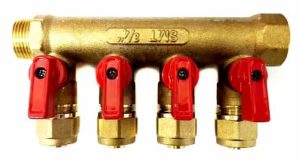
- A simple manifold is a tube with shutoff valves and internal and external threads. This model is inexpensive, but lacks a system configuration feature. Installing this manifold on underfloor heating systems requires additional components.
- Equipped with outlets from a valve for regulation and valves for connecting the circuits, this is a Chinese device. It often leaks, but repairs are easy—simply replacing the gasket. The distance between the supply and return pipes does not match European standards, so various accessories are required.
- The model with regulating valves and Eurocones is an expensive one. It doesn't have ball valves, but it does have fittings and adjustment valves, which can be equipped with an actuator to regulate the temperature in the main line.
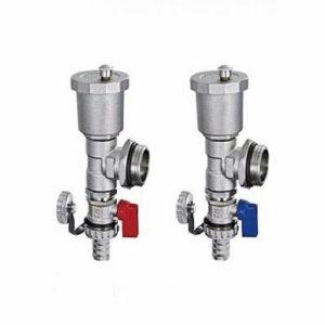
- With flow meters—they're located on the manifold's supply pipe, and the return pipe houses servo drive sockets. This device is designed for underfloor heating systems with circuits of varying lengths; the flow meters allow for the adjustment of the coolant volume in each circuit.
Each model is equipped with outlets for water and air drainage.
Operating principle
The general operating principle of the unit, regardless of the valve type (two- or three-way), is to distribute the water flow through the underfloor heating loops, circulated by a pump. The amount of coolant entering each branch is regulated mechanically or automatically by a servo drive.
The work process looks like this:
- The coolant heated to 60 - 80 degrees is supplied from the source to the comb through a thermostatic valve;
- A flow of cooled water from the return line comes from the distributor;
- The shut-off valve has a head that regulates the temperature of the liquid;
- The two mixed streams are fed into a mixing pump, and then the water is distributed through the pipelines.
When the heating temperature of the coolant in the main line drops to the required level, heated water from the source is mixed in, which is done by a two- or three-way valve.
The design of the collector cabinet
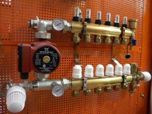
A manifold cabinet is a structure that includes a pump-mixing unit and a manifold block.
Pumping and mixing unit
This unit is designed to dilute the heated water entering the underfloor heating system with the used, cooled coolant. The mixing process is performed by the pump impellers.
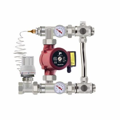
The pump delivers the diluted liquid to the desired degree into the system. As it moves through the pipes, it releases heat to the room and, once cooled, returns to the mixing unit.
The temperature is adjusted using balancing valves, which also regulate the flow of wastewater in the pipes. To heat a small room, the shut-off valve should be opened; for smaller rooms, it should be closed.
This underfloor heating manifold system is equipped with a thermostatic valve, which controls the temperature in the system. It opens or closes the heated water supply valve. When the coolant flow stops, the bypass valve opens, allowing the fluid to flow through the bypass.
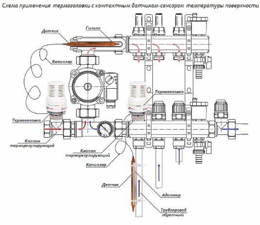
With a simple manifold piping method, temperature control is manual. To automate the process, an actuator with a thermostat is used. The actuator receives a signal from the thermostat regarding the room temperature and, based on this reading, opens or closes the return manifold damper, thereby regulating water circulation in the floor.
Key indicators characterizing the pumping and mixing unit:
- operating pressure - maximum value 10 bar;
- temperature level - +90 degrees (maximum);
- temperature range: from 20 to 60 degrees.
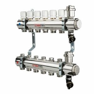
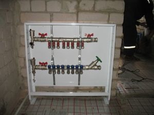
Collector block
The manifold cabinet is equipped with a unit responsible for regulating the water flow that enters the floor main and returns back.
Technical indicators:
- product diameter - 1 or 1.25 inches;
- number of branches - from 3 to 12;
- pressure (working value) - 10 bar;
- The maximum heating level of the coolant is +100 degrees.
In the collector block there are two rows of bypassesOne, the so-called direct row, is responsible for adjusting the volume of hot coolant, the other (reverse) regulates the cooled water.
Correct assembly of a manifold for underfloor heating
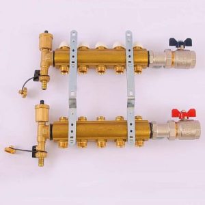
Assembling a factory-made manifold is a simple process. Included:
- distributor with rotameters, it is connected to the supply - has 2 or more branches for circuits;
- return comb with thermal valves instead of flow meters;
- automatic air vents;
- taps with plugs for supplying and draining water from the underfloor heating main;
- inlet and outlet temperature thermometers;
- Shut-off ball valves and brackets.
When purchasing the device, its accessories can be modified based on budget and the boiler connection method. It's acceptable to install a manifold without flowmeters or just one thermometer instead of two.
Assembly process
The factory-made unit is designed so that anyone can install it themselves. This means that the distribution parts are often sold pre-assembled; only the underfloor heating circuits and any auxiliary components need to be connected.
The equipment should be assembled in stages:
- The device is removed from the packaging. Factory-installed models already have flow meters and valves on the supply and return pipes. If the unit is divided into several parts, they should be screwed together.
- The manifold is secured to a bracket, which will allow for further assembly with greater convenience.
- The remaining parts are attached - air vent, valves, plugs and control devices.
- Ball valves are mounted on the return manifold.
The circulation pump and valves should be attached after the unit has been secured to the wall.
Installation of a heated floor manifold
Once you've assembled the basic components, you can begin installing and connecting the underfloor heating manifold. The process consists of several steps:
- Location and installation location. The standard height for mounting the manifold on the wall is 500–1000 mm from the floor. It should not be installed any lower, as connecting the floor pipes to it will be difficult. Furthermore, the manifold should be positioned so that all loops are the same length and easily accessible, preferably in the center of the room.
- Installing the manifold cabinet. A manifold cabinet is installed at the designated site. It typically measures 1 m by 1 m, with 12 cm thick walls. It can be placed in a dedicated niche or mounted directly to the wall. The wall surface must be level, otherwise the cabinet may malfunction.
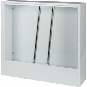
- Mounting the comb in the box. The cabinet is equipped with special guides that can be moved to the required distance, depending on the length of the manifold. These guides are equipped with fasteners (bolts) that secure the device to the box.
- The pump and valves (two- or three-way) are installed according to the planned diagram. First, a valve with a thermal head is installed on the supply pipe coming from the boiler. Then, the pump is mounted on flanges with union nuts; it should be positioned between the valve and the manifold. Do not install the pump upstream of the shutoff valve, as this will prevent the valve from functioning properly and the water flow will be improper.
Connecting the transformer substation to the collector
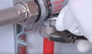
Connect the underfloor heating circuits to the manifold outlets using a threaded connection with a Eurocone fitting. The Eurocone is typically 17 mm in diameter, while the floor hose is 16 mm. Therefore, it will need to be calibrated to this size. Then:
- a union nut must be put on the tube, a compression ring and a thrust sleeve must be inserted;
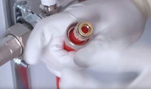
- manually connect the end of the hose to the comb fitting;
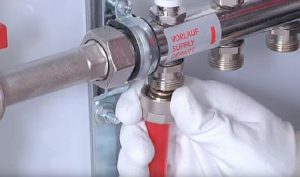
- Finally tighten with two wrenches - one to fix the hex key on the fitting, the other to tighten the connection.
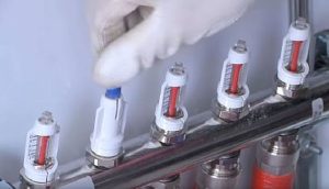
Collector setup
The process of setting up a collector for a water-heated floor is carried out according to the following instructions:
- removing the cap from the shut-off valve;
- securing the valve with a hex key;
- determining the number of turns for a specific loop;
- scrolling the valve for the calculated number of times.
The remaining underfloor heating circuits are configured in the same way.
The service life and quality of the floor depends on how accurately the adjustment is made.
Is it possible to install the manifold below the level of the heated floor, for example in the basement?
There are cases when the distribution and mixing unit must be installed not on the floor where the underfloor heating is installed, but below, for example, if the boiler room is in the basement, or you simply do not want to spoil the interior of the apartment.
This type of wiring is acceptable., the manifold installation is carried out in the same sequence as usual. There is only one problem - Automatic bleeding of air masses from the main line is not possible, if the air vent is located on the comb.
The solution is to install an air vent on the return pipe between the manifold and the floor hinges, and install a shut-off device with a shut-off valve upstream of it. Access to the air vent is essential.
Please note: Since an air vent is required for each floor line, it's worth considering installing the manifold below the underfloor heating system.
Underfloor heating is a modern heating system ideal for private homes. With proper installation of the floor structure and manifold, the system can provide comfortable indoor conditions.

I don't think installing the manifold itself is particularly difficult. The main task is to properly configure all the underfloor heating circuits. This ensures stable operation and maximum efficiency.