A sewer manhole is designed to maintain the sewer network's operational functions, including routine repairs and emergency interventions. Its main components include a working chamber with a manhole, above which is a hatch with a lid. Sewer manholes can be flush, inspection, or drop-type.
In the overall underground utility system, sewer manholes play a key role. This article explores manhole layouts, their structure, types, and installation features.
A sewer system is a complex engineering system consisting of numerous components that ensure the smooth operation of the entire network. Inspection chambers are classified by purpose:
- On the linear ones.
- On the rotary ones.
- And nodal ones.
Manholes are a key technical structure used by industry professionals to perform their duties: checking the collector's performance and, if necessary, cleaning pipes.
These facts indicate that a sewer inspection manhole is a critical point for ensuring the smooth operation of systems. This is especially true for underground utility lines.
- Locations depending on purpose
- Features of different types of sewer manholes
- Let's take a look at the device
- Types of sewer inspection wells
- Purpose of sewer inspection wells
- Sewer overflow well
- Installation from concrete rings
- Requirements for the installation of sewer structures
- Plastic sewer inspection structures
- Self-installation of viewing structures
- In conclusion
Locations depending on purpose
The installation of inspection chambers is regulated by construction documents. According to SNiP, inspection points are installed at bends and slopes when changing line pipelines, as well as at the junction of the central line and additional branches.
Sewer system outlets for private residents are possible with the installation of inspection chambers. The diameter of the installed pipe is directly affected by the distance it is laid (linear section).
For pipelines up to 35 meters long, elements with a diameter of 150 mm are used. An inverse relationship exists. For example, if the diameter of the pipes entering the general pipeline system is 150 meters, then the installation requirements require an inspection manhole every 35 meters. An industrial monitoring system can be fundamentally different from similar systems installed in the private sector.
Features of different types of sewer manholes

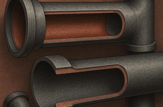
The structure of a sewer manhole is a round, rectangular or polygonal shape, consisting of:
- From the base.
- Tray.
- Working chamber.
- Both the neck and the hatch.
The technical structure is based on a tray made of grade 200 concrete using formwork. However, this is not the only option. Brick, reinforced concrete blocks, or rubble stone can also be used.
Let's take a look at the device
The inspection shaft kit includes a certain set of working elements:
- A reinforcing frame, which can be square or round. A staircase is installed inside the structure.
- The bottom of the structure is a smooth lower floor. It can be equipped with channel profiles.
- The upper ceiling, where an opening for a hatch is provided.
- A working (protective) hatch. It can be circular or square. Its outer surface is marked to indicate the type of manhole.
The main material of the reinforcing frame is reinforced concrete. The reinforcing frame is assembled using concrete rings. The bottom is a round slab.
The bottom of sewer manholes can be filled with concrete mortar, which is supplied to the base of the formwork object.
The upper part of the structure is designed to accommodate a hatch.
 Thanks to modern technology, sewer manholes can be constructed from other materials. Manhole inspection structures can be constructed from materials other than reinforced concrete.
Plastic is the primary working element and competitor to precast concrete. Manholes deserve special mention, as they are of great importance. They can be:
- Cast iron.
- Steel.
- Polymer.
Naturally, steel manholes are more durable than other elements. If the inspection facility is located on a busy highway or road, a metal manhole or cast-iron grating is installed in its place.
Types of sewer inspection wells
Shafts or chambers that are installed above the pipeline that drains water are classified according to their internal structure:
- as controls;
- filtering;
- front type;
- as storage devices.
Regardless of the type and/or purpose, all of these are included in the project design (design and estimate documentation) for the facility. The sewer manhole drawing is prepared by specialists from the design organization based on the specified technical specifications.

Purpose of sewer inspection wells
A junction inspection shaft is designed at the junction of several pipelines. The sewer line is connected to the channel by a smooth curve. Manholes designed for inspection of large sewers are called junction chambers.
The structure in question is installed on a straight section of the existing pipeline and serves as a point for inspection and maintenance of the system. The operating distance is primarily determined by the diameter of the installed pipe. Based on the following parameters:
- up to 155 mm – 3500 mm;
- from 200 mm to 450 mm – 500 m;
- from 500 mm to 600 mm – 750 m;
- from 700 mm to 900 mm – 100 m;
- from 1000 mm to 1400 mm – 150 m;
- from 1500 mm to 2000 mm – 200 m;
- more than 2000 mm – 250000-300 m.
An increase in the working distance between inspection objects of up to 10% is permitted. For collectors designed for water flow transit with a diameter not exceeding 2,000 millimeters, the inter-well distance may be increased to 300 meters.
To reduce high hydraulic pressure between the outlet and connecting pipe, the working angle should be at least 900 (degrees). The turning radius accommodates 1 to 5 pipes, where the tray has a smooth curve. Its purpose: to clear the inlet pipes of possible blockages.
Sewer overflow well
 It can be of five types:
- the shaft bends are carried out upwards and downwards;
- in the form of a glass;
- with vertical water damper;
- multi-stage option;
- with corner overflow channel.
A brick sewer well includes:
- Bottom, with a single-level highway.
- Walls.
- Open tray.
- Floor slab.
- Protective hatch.
- And also wall brackets.
To carry out work and lower service personnel, the diameter of the device must be more than 1 meter.

Installation from concrete rings
More details about For information on installing sewerage systems using concrete rings, see this article..
 Initially, a pit is dug based on the soil conditions for the pipeline. Once the excavation is complete, a bedding material is laid, consisting of coarse or medium-sized crushed stone.
The bedding is approximately 1,500 mm thick. This element helps prevent subsidence of the entire structure.
After completing the above steps, a layer of hydraulic insulation is installed. This can be a roll or sheet. The tray formwork is placed on top of the insulation layer. A prefabricated slab can also be installed.
The next stage is the transition to shaft construction. The wells, made of concrete, are assembled in the ground pit, where the working elements have not yet been installed.
Requirements for the installation of sewer structures
Installation is carried out in strict accordance with SNiP and is regulated by GOST No. 2080-90, which stipulates that sharp turns in the system's routing are not allowed. The angles of the inlet and outlet pipes must be maintained.
- The working elements are made of fine-grained concrete in compliance with recommended standards.
- The tank must be equipped with reinforcing bars to evenly distribute the load and consist of reinforcing wire.
- Before installation, it is necessary to prepare a working plan and carry out preparatory work, which includes clearing the site and removing vegetation, including trees.
This is not a complete list of recommendations and working conditions, which are fully reflected in the relevant documents.
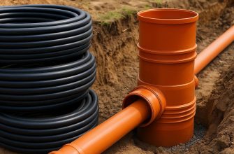
Plastic sewer inspection structures
Plastic products are becoming increasingly popular. They are distinguished by their ease of assembly and the environmentally friendly materials used in their construction.
Self-installation of viewing structures
Yes, this option is possible. However, DIY installation entails certain costs and extensive preparatory work, which is unlikely to be accomplished on your own. Connecting the system to a private home can differ significantly from generally accepted principles. This may be due to the nature of the structure, the groundwater level, and the structure of the work site.
The operating principle is no different from industrial installation. There are numerous instructional videos online, and technical literature is sufficient. Therefore, there's no point in going into detail about this issue.
In conclusion
In summary, the following can be noted. There are many different designs for different types and purposes. When choosing an installation, the recommendations of many services are taken into account, and the optimal option is selected.
Initially, paperwork is carried out: a drawing is created and the installation of the structure, which can be made from different materials, is carried out according to it.