You ask what the air speed in the duct should be, I will answer – from 0.3 to 30.0 m/sThe value depends on the type of ventilation, components, and operational factors.
In this article, I'll discuss the impact of duct cross-section on air flow rates. I'll explore natural and mechanical ventilation systems for residential, public, and industrial buildings. I'll also answer frequently asked questions.
- The influence of duct cross-section on air velocity
- Rectangular air ducts
- Circular air ducts
- Air ducts with natural and mechanical induction
- Natural ventilation ducts
- Mechanical ventilation ducts
- Air ducts for buildings of various purposes
- Residential and public buildings
- Warehouses and production
- Local systems and aspirations
- Smoke ventilation
- How does speed relate to ventilation performance?
- Answers to frequently asked questions
- Video materials
The influence of duct cross-section on air velocity
The size and shape of the duct affects airflow speed in ventilation systems. These ventilation duct parameters are often collectively referred to as their cross-section.
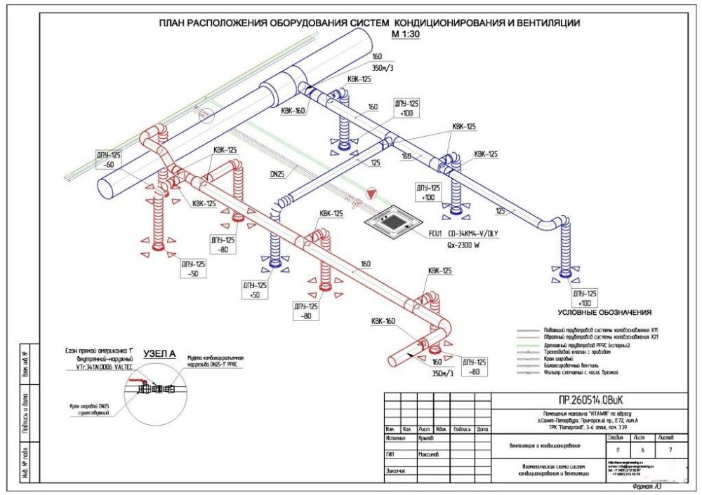
Engineers developing a ventilation project first think through the layout of the internal wiring within the building space and calculate the length of each section.
The length of the ducts and the number of bends with diameter differences affect the airflow in the utility network duct. With a diagram and the specified flow rates for each section, engineers determine the duct cross-section.
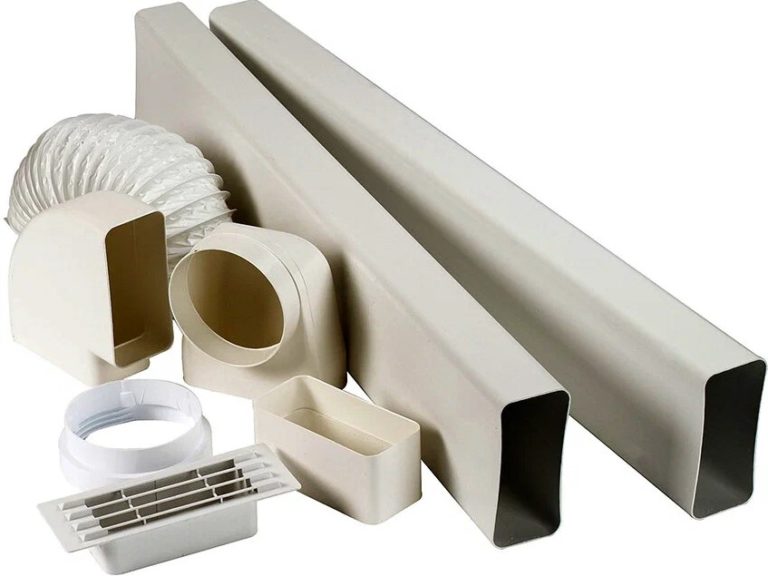
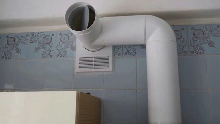
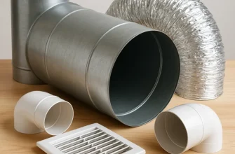
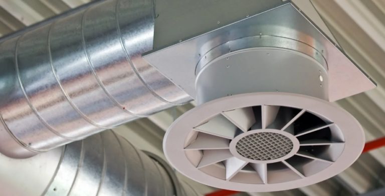
Ventilation ducts are round and rectangular shaped fittings. Galvanized sheet metal is a common material used. Manufacturers also produce ducts made of stainless steel and plastic.
In older high-rise buildings, common utility ducts are made of brick, cinder block, plaster, and bare masonry. Rubber ducts are used in specific applications.
Using different materials allows for ventilation ducts to be tailored to the operating conditions. A plastic pipe running from the kitchen hood is aesthetically pleasing.
Metal channels are suitable for areas with high operational and external mechanical loads.
Plastic, galvanized steel, stainless steel, and other materials each have their own surface roughness rating. This rating affects air movement speed.
Engineers take into account the roughness of the ventilation duct's internal walls. Tabular data for the calculations is freely available.
| Air duct material | Roughness coefficient (K, mm) |
| Metal | 0.1 |
| Plastic, vinyl | 0.1 |
| Slag gypsum | 1 |
| Cinder concrete | 1.5 |
| Brickwork without plaster | 5-10 |
| Brickwork with plaster | 3-6 |
| Plaster applied on mesh | 10 |
| Rubber | 0.006-0.01 |
Rectangular air ducts
Rectangular ducts are designed for specific applications. Their limited use is due to two factors:
- The rectangular channel has low aerodynamic characteristics.
- Compared to a round pipe, a rectangular duct is more difficult and expensive to manufacture.
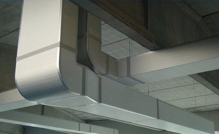
A rectangular box can withstand less pressure than a round pipe. The advantage is that the flat walls allow the ducts to be routed under ceiling lining or inside narrow ventilation shafts.
The standard size of shaped parts is regulated GOST R 70349-2022When designing ventilation systems using rectangular ducts with non-standard cross-sections, the aspect ratio of the air ducts should not exceed 1:4. For natural ventilation systems, the aspect ratio of rectangular ducts is limited to 1:2.
When designing ventilation, engineers determine the permissible air velocity based on the following factors:
- permissible level of aerodynamic noise according to SP 51.13330.2011;
- permissible indicator of operating pressure loss in the ventilation network.
The air velocity in a rectangular duct is calculated using the formula: V = L x 1,000,000 / (3600 x W x H).
Under the meaning L substitute the air flow rate specified by the project for a specific area, measured in m3/hour. Value W, H – width and height of the walls of a rectangular channel (mm).
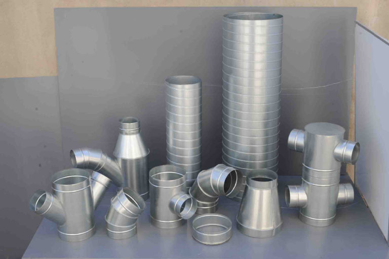
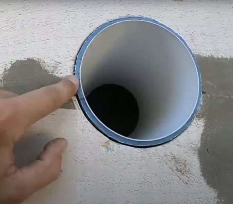
Circular air ducts
Round air ducts are larger than rectangular ones, making installation more challenging. The utility system takes up more space but offers improved aerodynamic performance.
The airflow noise level is lower compared to a rectangular duct. A round duct can withstand greater internal pressure and external mechanical loads than a rectangular duct.
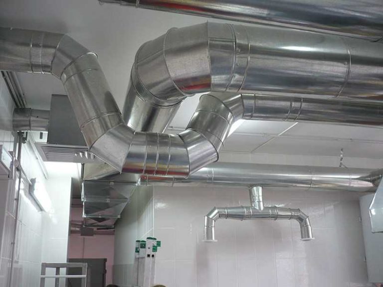
Cylindrical duct technology is less expensive to manufacture. Pipes are easier to install by attaching them to building structures. These operational advantages have made round shaped components popular for ventilation systems.
When ventilation calculations are made for rectangular ducts, but the use of round pipes is permitted, the equivalent diameter term is used.
The interchangeability of air ducts of different shapes and diameters is determined by: D = 2AB/(A + B). The values of A, B are the sides of a rectangular box (width and height).

For a rectangular duct, equivalent refers to the nominal diameter of the air duct where the operating pressure losses due to friction are equal. To avoid complex interchangeability calculations, in practice, circular pipes are preferred when developing ventilation designs.
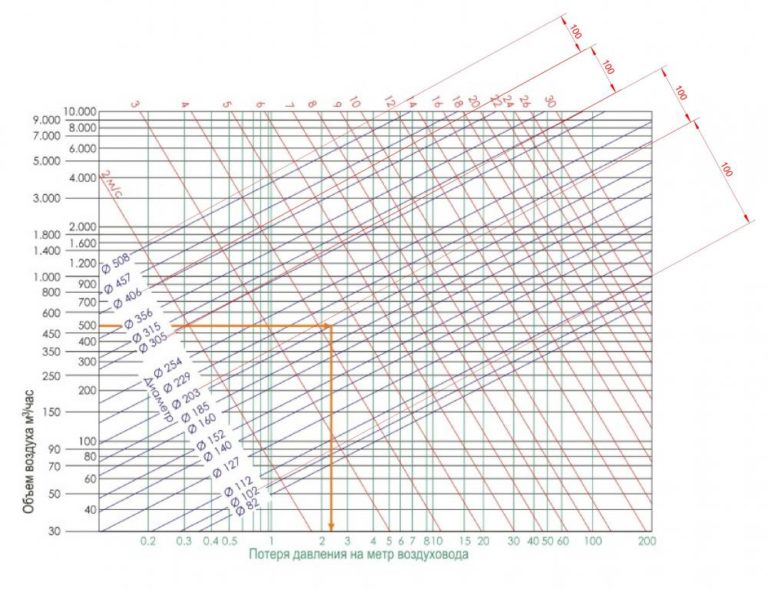
The aerodynamic parameters of utility networks are calculated using specialized software, using tabular data from reference books. Dynamic pressure calculations are based on diagrams with an error margin of 3-5%.
The mathematical formula for air velocity in a circular duct is as follows: V = L x 4 x 1,000,000 / (3600 x 3.14 x d2).
The value L is the air flow rate specified by the project for a section of the pipeline, measured in m3/hour. The value d refers to the internal diameter of the pipe.
Air ducts with natural and mechanical induction
Ventilation networks have air flow velocities ranging from 0.3 to 30.0 m/s. Air is transported mechanically or naturally. Ventilation standards have been developed based on the specific space, area, and number of occupants.
Regulatory documents do not provide precise figures for maintaining the recommended ventilation network speed.
The parameter is determined by engineers during project development and depends on:
- categories of architectural structures;
- the intended purpose of the building and separate premises;
- cross-section and material of ventilation ducts;
- presence of insulation of ventilation ducts;
- number of shaped elements;
- presence, quantity of adjustment and throttle units.
Secondary factors specific to the ventilation object are taken into account.
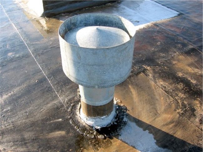
Natural ventilation ducts
Natural ventilation systems move air currents according to the laws of physics without the use of fans. Circulation is created by temperature and pressure differences.
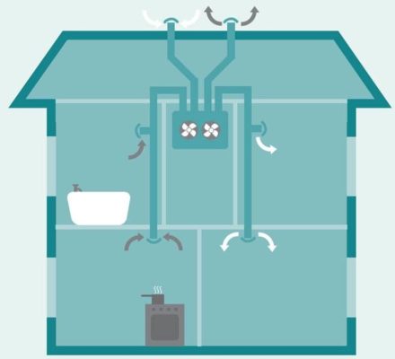
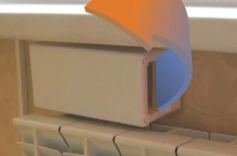
Warm air inside the room is directed upward and discharged through the exhaust duct to the outside. Cold air enters the room through an intake vent located on the lower part of the wall.
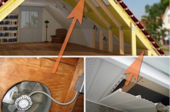
Naturally ventilated air ducts were previously installed in older apartment buildings. They are now used in private homes and utility rooms.
Air movement speed depends more on natural factors than on human influence. In windless weather, draft may be absent or reversed.
No regulatory documents have been developed. There are reference books that provide recommendations for air velocity standards in naturally aspirated ducts:
- Wind networks with a deflector and a pressure of 5-6 Pa have a speed range of 1-1.5 m/s.
- Gravity networks at temperature differences 5OC and a pressure of 3-4 Pa have a speed range of 0.5-1.5 m/s.
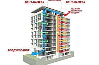
Inside the common-building exhaust shafts of buildings with 4-12 floors, at a pressure of 6 Pa, the natural air velocity in the duct reaches 2 m/s. Velocity ranges for other ventilation sections are shown in the table.
| Ventilation unit | Recommended flow rate (m/s) |
| Ventilation grilles | 0.3-0.6 |
| Vertical air ducts | 0.5-1 |
| Horizontal collection channels | 0.6-0.8 |
| Hoods | 1-1.5 |
The reference books do not contain recommendations for air flow rates for high-rise buildings with more than 12 levels and a temperature difference of 6OC. Engineers calculate the indicator individually using an extended scheme.
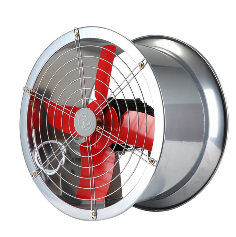
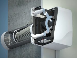
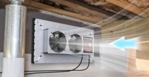
Mechanical ventilation ducts
A utility system where air is moved by the force of fans is called forced or mechanical. The air flow velocity depends on the motor power and the cross-section of the air ducts. The environment has little effect on the intensity of mechanical air movement.
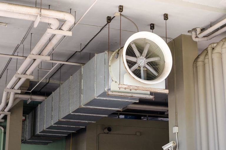
Utility networks are in demand for new multi-unit residential buildings and private homes. Mechanical ventilation is designed for enterprises, public buildings, and agricultural farms.
- Engineers use the permissible velocity method during the ventilation design stage. The optimal velocity is used as the basis. To determine the operating parameter, the duct cross-section and pressure drop are determined for each section of the network.
- The dynamic pressure method is used at the design stage or during the feasibility study of a ventilation network. It is based on the pressure loss per linear meter of the system section. After determining the optimal air flow rate, the duct cross-section is calculated.
Of the two methods for determining air velocity, the simple dynamic pressure method is considered approximate.
Air ducts for buildings of various purposes
The intended purpose of an architectural structure is not defined by its general name. A residential building is considered to be a private or multi-apartment building.
A public building can include an office, a store, or a library. Engineers design ventilation systems for each building based on its specific purpose.
Residential and public buildings
The aerodynamic noise level is proportional to the air velocity in the ducts. The sound power level is calculated using the formula: Lw = 10 + 50 log (v) + 10 log (A). The value of v is the air velocity (m/s). The value of A is the cross-sectional area of the ventilation duct.
The design engineer's task is to determine the flow rates within the ducts so that the ventilation system provides the required air exchange without exceeding the permissible aerodynamic noise level. The location of the ventilation system is taken into account.
Let's take a residential space as an example. The recommended air flow rate inside rectangular boxes under a suspended ceiling is 5 m/sIf the channels are laid throughout the room, the indicator is reduced to 2 m/sFor round air ducts, other speed values are recommended – 3 and 4 m/s respectively.
Using a public building as an example, consider a store, a school classroom, or a conference room. The recommended air flow rate inside rectangular ducts under a suspended ceiling is 8 m/sFor channels laid throughout the premises, the value is reduced to 7 m/sFor round air ducts, the recommended speed values are: 8 and 6 m/s respectively.
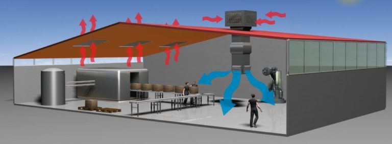
Warehouses and production
Ventilation of warehouse and production facilities is designed to be mechanical. There are no air velocity restrictions.
The aerodynamic sound level generated by the flows, combined with industrial noise, must not exceed established standards. Recommended examples are freely available and can be found in the table.
| Name of the object | Recommended flow rate (m/s) |
| Warehouse without permanent human presence | 16-20 |
| A warehouse with people constantly working | 10-14 |
| Workshop with workstations | 14-22 |
| Secondary premises | 10-12 |
| Changing room, staff break room | 8-10 |
Local systems and aspirations
When dust concentrations in local systems and aspiration systems exceed 0.01 kg/kg, engineers calculate air ducts using the dynamic pressure method. In other cases, the permissible air velocity method is used, based on the optimal air velocity.
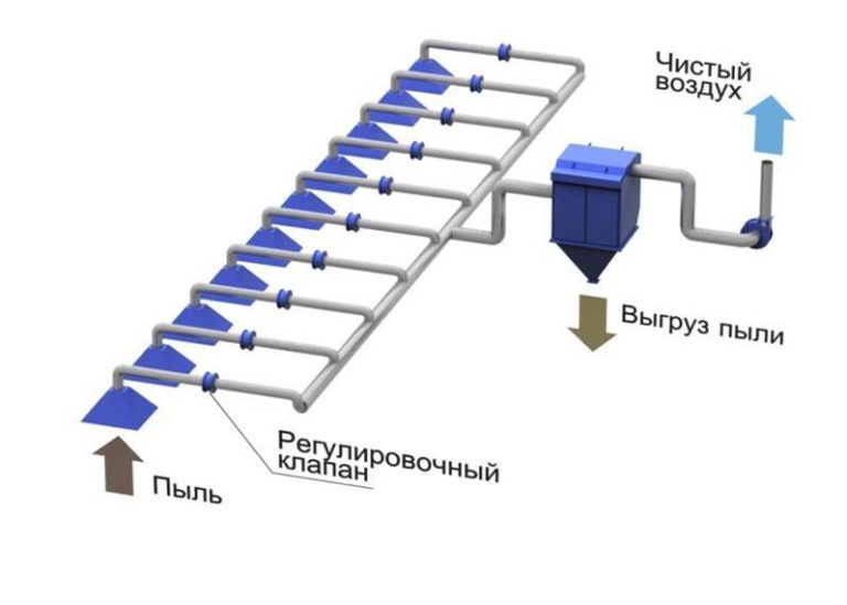 Local systems and aspiration systems typically maintain high-velocity air movement. Short networks have a limited number of nodes that create resistance.
Air velocity is maintained above the particle velocity of the transported material, preventing sediment accumulation on the channel walls. The average air velocity range is 15-30 m/s.
To obtain accurate calculations, engineers use departmental reference books and tables.
| Purpose of the system and aspiration | Velocity flow (m/s) |
| For bulk solids | 12-20 |
| For moisture and warm air | 12-16 |
| For dust and gaseous substances | 14-16 |
| For the welding station | 8-14 |
| For woodworking equipment | 16-20 |
| For sanding equipment | 18-22 |
| For chemical baths | 6-8 |
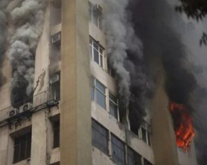
Smoke ventilation
The average smoke ventilation air flow rate is 15-20 m/s. This figure is calculated for the air-smoke mixture.
The flue gas temperature at each section of the network is taken into account. Engineers use reference books and ready-made tables to calculate mass flow rates.
| Network section with flue gas temperature of 300OWITH | Mass velocity index (kg/(s*m2)) |
| Valve body | 8-10 |
| Vertical channel | 14-15 |
| Horizontal channel | 10-14 |
| Channel after the fan | 15-16 |
How does speed relate to ventilation performance?
The ventilation network must ensure adequate air exchange within the building without creating discomfort for occupants due to excessive noise levels. Sanitary standards have been developed to ensure the high performance of the utility network.
The recommended indoor air velocity is 0.3 m/s. Exceeding this standard by up to 30% is permitted during renovations. Large warehouses, production facilities, and garages typically have two ventilation systems, distributing the load equally.
Example of minimum and maximum noise levels for hospitals: during the day – 35-50 dB, and at night – 25-40 dB. For residential premises, other thresholds are set: during the day – 40-55 dB, at night – 30-45 dB.
In addition to noise waves, vibrations from ventilation ducts can also cause discomfort. This can occur due to loose connections, narrowed ducts, and other factors.
As the speed of air movement increases, the vibration of the system increases if the structure is designed or installed incorrectly.
Standards for permissible values of local vibration are contained in reference books for specialists who design and commission finished ventilation networks.

Airflow rate affects the rate of air exchange within a room per unit of time. This parameter is calculated using the formula: N=V/WThe V value is the volume of clean air entering the room in 1 hour. The W value is the volume of the room itself.
Ready-made multiplicity standards for various types of facilities are readily available in tables. Let's take a combined bathroom as an example. 50 m are replaced per hour.3 air, and the flow rate in the air ducts ensures that the standard parameter is achieved.
Answers to frequently asked questions
The recommended parameter for residential premises is 0.3 m/s.
Recommended value: wind networks with a deflector and a pressure of 5-6 Pa – 1-1.5 m/s. Gravity networks with a temperature difference of 5 °C and a pressure of 3-4 Pa – 0.5-1.5 m/s.
To take measurements, use an anemometer.
Place the anemometer sensor near the vent at the distance recommended by the manufacturer. The display will show the result.
Knowing the air flow rate (L) and the cross-sectional area (S) of the ventilation duct, calculate the flow velocity (V) using the formula: V = L / 3600× S. To measure without mathematical calculations, use an anemometer.