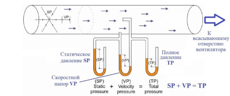
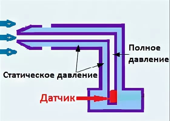
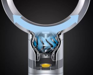
By definition, the static pressure of a fan is, This is the pressure created by the operating ventilation unit, proportional to the air velocity squared.
Additionally, ventilation equipment forms dynamic and total pressureWe'll discuss defining quantities, measurement rules, and formula-based calculations in this article.
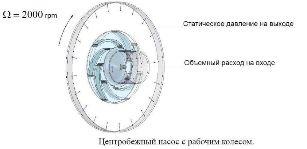
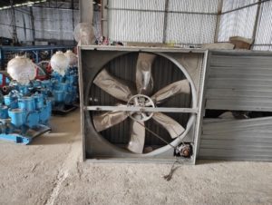
Static pressure
In technical language fan static pressure, This is the resulting value of air pressure resulting from the operation of the ventilation unit. This indicator is typical for a network where there are no air flows or where air is freely released into the atmosphere.
Unlike dynamic and total pressure, static pressure (P) is proportional to the square of the air velocity. This value increases as the ventilation equipment rotor speed increases.
For calculations it is customary to use the formula: P = (ρ x V2) / 2.
The letter designation means: ρ – density, V – air speed.
On the magnitude of the statistical pressure created by the fan, 3 main factors influence:
- Dimensions and shape of the ventilation unit.
- Number of blade revolutions.
- Efficiency of ventilation unit.
As ventilation equipment grows larger, air mass capture increases. Proper blade and housing design directly impact efficient air transport, resulting in higher static performance.
Increasing blade speed accelerates airflow. As air flow increases, the static pressure rises. Simultaneously, noise in the ventilation system increases, and rotor bearing wear accelerates.
Efficiency refers to the useful performance of a ventilation unit. This parameter reflects how effectively the airflow energy generated by the rotating blades increases the static value.
The test is based on different equipment with the same rotor speed. A more efficient fan, which has greater performance at a lower noise level without increasing the speed.
The static indicator determines the efficiency of a fan used in equipment and mechanisms:
The static value is the determining factor when choosing ventilation equipment based on technical characteristics.
Dynamic pressure
Unlike static and complete, fan dynamic pressure In hydrodynamics, this is called velocity. Its value in formulas is denoted by the letter q or Q and is measured in pascals or mm of water column.
The formula for calculating the velocity value: q = 1/2 · ρ · ʋ². The letter designation means: ρ is the density of air masses (kg/m3), ʋ² – flow velocity (m/s) squared.
Ventilation systems do not create conditions under which air compression increases density. The constant ρ value in the calculation formulas is assumed to be 1.2 kg/m³.
The dynamic index can be considered as kinetic energy per unit volume of the working medium. The Bernoulli equation is used for calculations: Q o – Q s = 1/2 · ρ · ʋ². The designation refers to pressure: Q o - general or complete, Q s - static.
When the air flow is suddenly stopped, a dynamic value equal to the difference between the stagnation pressure and the static pressure will be created in the stagnation zone. This parameter should be measured with a device at the stagnation point.
When a ventilation unit is operating, a vacuum is created at the air intake. At the outlet, an elevated pressure is created. The difference in these values creates dynamic pressure. This parameter must be measured at two points—at the fan inlet and outlet.
The dynamic value indicates the force exerted by the air handling unit's blades to move air through the duct system, taking into account resistance. Resistance can include bends, curves, control units, and narrow duct cross-sections. The material and configuration of the ducts also create resistance.
Let's take a perforated fabric duct used in industry as an example. As the duct lengthens, the airflow volume and velocity decrease. At the outlet of the duct, the dynamic pressure decreases, while the static pressure increases.
Due to the gradual reduction in air volumes transported, friction losses against the duct walls are neglected. At the pipeline outlet, the increased static pressure is equal to the total pressure.


Knowing the dynamic pressure is important:
- when designing ventilation for the correct determination of technical parameters of equipment and air ducts;
- when testing ventilation equipment for performance.
The correct result obtained in the dynamic value calculations ensures optimal ventilation efficiency. Air flows at the duct outlet will be created with speeds and volumes that meet design requirements.
Full pressure
A ventilation network cannot operate without static and dynamic pressure. The combination of these values creates a third value. By definition, total fan pressure, this is the sum of the static and dynamic indicators.
The total fan pressure is calculated using the formula: Qp = Qo + QsThe abbreviation denotes pressure: Q o - general or complete, Q s - static.
The total fan pressure must be determined during the ventilation network design phase. Calculated data is used to determine the suitability of the equipment's performance characteristics for ventilation.
Inlet pressure measurements are taken in the fan duct cross-section. The recommended location for the data collection point is a distance equal to two duct diameters. A straight duct four times the diameter of the duct should preferably be located in front of the measurement point.
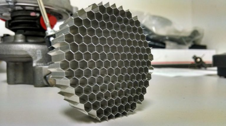
When conditions do not allow full measurement at the input fan air pressure, A honeycomb is installed in the desired location. The technical unit, a grid, equalizes airflow. The cells are 5-10 mm long and have a wall thickness of 0.5-2 mm. A receiving device is inserted into the channel. Data is taken at at least three points along the cross-section, and the average value is calculated.
Measuring the total outlet pressure is complicated by the non-uniform flow structure. The resulting return air masses interfere with velocity determination. To even out the flow, install a honeycomb or measure the pressure at a distance of 7-10 duct diameters from the outlet.
The elbow and breakaway diffuser complicate the measurement process. The outlet assembly increases the non-uniformity of the flow. Measurements are taken as follows:
- The probe scans several points to determine the average total pressure and equipment performance. The first cross-section immediately downstream of the ventilation unit is used as the measurement location. The result is compared with the performance value obtained by inlet measurements.
- Additional measurements are taken on a straight section. Select the first level section of the duct running from the air handling unit outlet. Measure a distance of 4-6 diameters from the start of the straight duct. On a short duct, use the furthest point. Scan the section with a probe, and calculate the average total pressure and air flow.
The calculated loss in the duct section downstream of the fan is subtracted from the average total pressure, additionally measured on the straight section. The resulting total pressure at the outlet is considered the final value.
Answers to current questions
The velocity value is calculated using the formula: q=1/2 • ρ • ʋ². The letter designation means: ρ is the density of air masses (kg/m3), ʋ² is the flow velocity (m/s) squared.
In hydrodynamics, this indicator is considered a velocity indicator. The value indicates the force a fan can pump air through a system of channels, taking into account resistance.
Ventilation equipment creates static, dynamic and total pressure.
The coefficient is considered to be the ratio of the difference in pressure at the outlet and inlet of the ventilation equipment to the kinetic energy created by the air flow at the fan inlet.
For calculations, the formula used is: P = (ρ x V2) / 2. The letter designation means: ρ is the density, V is the air velocity.
The indicator determines the efficiency of a fan operating as part of an engineering network, other equipment and mechanisms.