A hydraulic test (pressure test) is a test of a closed system using air or excess pressure exceeding the normal operating value. It is performed to detect leaks or to determine how the system performs under extreme conditions. If the test is successful, the system will definitely withstand normal operating conditions.
Hydrotesting of pipelines is the most commonly used type of non-destructive testing that determines the strength and tightness of a pipeline operating under pressure.
 In most countries, it is accepted practice that pipelines and equipment operating under pressure must undergo hydraulic testing in the following cases:
- after the production of network parts prepared for installation;
- upon completion of pipeline laying;
- when monitoring the network during testing.
All process pipelines undergo hydraulic pressure testing in accordance with the standards SNIP III-G.9 – 62 and NITUHP – 62In addition, pneumatic testing is also performed. The latter is used in situations where hydraulic testing is not possible for the following reasons:
- Minus air temperature.
- When there is no water.
- Dangerous voltages in the pipeline due to the mass of liquid.
In addition to these methods, networks are tested using air or inert gas.
Testing of structures is carried out under the supervision of the manufacturer or foremen, and in strict accordance with the requirements of the project or instructions with the requirements of the State Mining and Industrial Supervision Authority.
Before work begins, the entire length of the main line is divided into separate sections. The entire network is then thoroughly inspected and the technical documentation is verified. At this stage, drain and air bleed valves and temporary plugs are also installed.

The use of shut-off valves is prohibited in this case.The line being tested is connected to a hydraulic pump, press, or other device that achieves the required pressure level.
Pressure during pipeline testing
The pressure during hydraulic testing of pipelines is checked with pressure gauges, which must first be check and seal.
According to GOST 2405-63, these mechanisms must have an accuracy class of at least 1.5. Their housing volume cannot be less than 15 cm3, and the scale for the nominal pressure reading must be no less than three-quarters of the measured pressure.
Hydrostatic testing tests systems not only for strength but also for density. The test pressure varies, depending on the application. For example:
- For steel and cast iron pressure systems, the design factor specified for them is 1.25. The test pressure increase above the working pressure cannot exceed 5 kg/cm², and the test pressure level cannot exceed 10 kg/cm².
- Asbestos-cement pressure systems are designed for a working pressure not exceeding 5 kg/cm2.
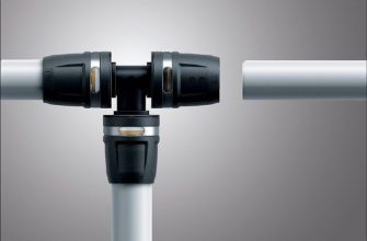
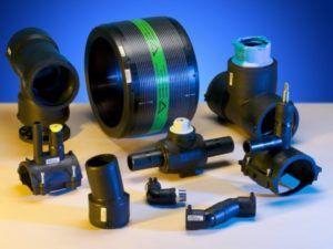
- Polymer systems are tested under the pressure specified by GOST or TU for a specific type of pipe, and this indicator is not allowed to be reduced below the operating level.

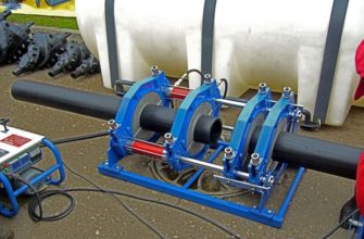
To create the required pressure during hydraulic testing, use:
- Hydraulic presses.
- Manual piston pumps.
- Gear driven pumps.
- Operational pumps.
How is testing conducted?
- Connecting the hydraulic pump.
- Installation of pressure gauges.
- Filling with water (during this procedure, the air vents should be left open until water appears in them, indicating that air pockets have been completely flushed out of the network). Once water is added, the main line is carefully inspected; leaks will indicate any defects.
- Creating working pressure using a press or pump and maintaining the network under it for a certain period.
- Reducing the pressure level to the working level.
- Removing liquid from the network and conducting a secondary inspection.
- Dismantling the pressure gauge and pump.
 The nets are held under test pressure for five minutes. Glass structures are the only exception to this test; they are held for twenty minutes.
The system is inspected after the pressure has been reduced to the operating level. When testing steel systems, the welded joints on both sides (at a distance of two centimeters) are tapped with a rounded hammer weighing no more than one and a half kilograms.
Non-ferrous metal pipelines are tapped with a wooden hammer weighing no more than 0.7 kg. Tapping of structures made of other materials is not recommended.
Carrying out the procedure of hydraulic testing of process pipelines
Hydrotesting of process pipelines is performed to determine the pipeline's density during caulking and leaks. The network is first tested before backfilling the pits and installing reinforcement.
Subsequent testing is conducted at the final stage after the trenches are fully backfilled and all work on the process systems in that section is complete. Preliminary testing can be performed once the connections have reached the required strength.

Any process pipeline is considered to have passed inspection if it has not ruptured or lost its seal. Also, if the joints remain intact and no leaks have developed.
Upon completion of the process system testing, they are immediately backfilled with soil and undergo final testing. During this process, the process systems are flushed with water, and the areas being tested are isolated from the operating system using flanges or plugs.
Before testing, the network and socket joints are flooded with water and left to stand for 24 hours. The final test is performed without safety valves and hydrants. Plugs are installed in their place.
The valves are then fully opened, but first the condition of the seal packing is checked. Use valves to shut off The zone being tested cannot be separated from the functioning zone.
Testing scheme
The pipeline hydraulic testing scheme consists of the following components.
- The system under test.
- Supports.
- Flanges.
- A valve that serves to release air pockets.
- Temporary water supply line.
- Press (hydraulic type).
- Pressure gauge.
- Adjustment tap.
- Side tap.
- Measuring tank.
During testing, the end sections of the main line indicated in the diagram are covered with blind flanges and secured with stops. After this, the main system is filled with fluid from the temporary main line (also included in the diagram).
While performing these steps, carefully ensure that air is released through the valve. This valve is installed at the highest point in the line (this is also indicated in the diagram).
The diagram also shows the pumps that generate the required pressure level.
IMPORTANT! When testing, be aware that pipes may rupture and fragments may fly. Therefore, precautions must be taken to prevent injury.
Testing and SNiP
After the installation work is completed, hydraulic testing of pipelines is carried out in accordance with SNIP III-G.9 – 62 and NITUKH – 62.
SNIP (Construction Norms and Regulations) stipulate that the system must undergo mandatory testing. SNIP regulations also establish a temperature range for work, ranging from five to twenty degrees Celsius.
SNiP (Building Code of Practice) regulations do not prohibit preliminary inspections by construction and installation companies without the participation of clients. However, according to the aforementioned regulations, test results are recorded in the work log.
After this, the pressure is increased to the test pressure and maintained for two hours. The pipeline is considered to have passed the final test if the pressure drop during the final two-hour period does not exceed 0.02 MPa.
According to the instructions, the network for heating load is connected only after the final backfill.
If the instructions don't specify a specific time for testing, it's determined by the duration of the system inspection. If defects are discovered during the inspection, according to the instructions, they can only be corrected after the pressure has been reduced to atmospheric pressure.
The instructions further state that after the detected defects have been corrected, testing is repeated again.
Necessary equipment
Equipment for hydrotesting pipelines allows for the leak testing of re-laid networks, and also provides the ability to create the required pressure level to test the network for poorly executed connections.
Equipment for this type of testing has a wide range of applications. For example, to select a pressure tester, you must first determine the maximum pressure required for the test.
The second significant point is the hydraulic pump drive. In this line of equipment, it can be manual and electric type.
Electric pumps for pipeline hydraulic testing. They are used to generate pressures up to 40 kg/cm². These devices are versatile and suitable for large system sizes. These devices are essentially high-pressure hydraulic pumps equipped with glycerin pressure gauges.
This equipment also includes a water reservoir and a hose that quickly connects to the fitting. The desired pressure level is set on the relay, and the pump will stop automatically when the desired pressure is reached.
Testing heating systems
Hydrotesting of heating pipelines ensures the normal functioning of the network During the heating season, this is a kind of exam and technical check of the heating system.

Each type of room has its own pressure characteristics. This pressure determines the circulation of the coolant and the heating of the room. As the coolant moves, various hydraulic processes occur, sometimes of a very severe nature.
For this reason, the heating pipeline is tested under pressure forty times higher than the working pressure.
When checking the heating network:
- Carrying out testing of cranes.
- To improve tightness, additional gland seals are installed.
- They are restoring the insulation on the pipes.
- The house is cut off from the general network with blind plugs.
- During installation, the main line becomes heavily clogged, so flushing and pressure testing are important steps towards ensuring the efficient operation of the heating network.
Winter testing
 Hydrotesting pipelines in winter differs from similar procedures performed in warmer weather. If a pipeline needs to be tested in subzero temperatures, measures must be taken to prevent water from freezing in the network.
In this case, the system is reliably freed from water in the following ways:
- The main line is preheated or hot water is pumped through it. Its temperature cannot exceed 60 degrees Celsius. During these steps, the drain fittings and drain lines are insulated.
- Testing the pipeline with aqueous solutions that freeze below 0°C is performed. This is immediately followed by flushing the pipes with heated water and purging them with air. If a calcium chloride solution is used for testing in winter, testing is performed on sections no longer than 1000 m (with a depth of up to 10 cm).
- In winter, a pipeline with a volume of up to 25 cm can be checked over a section of up to 250 m.
The required amount of water for testing in winter can be found in special tables.
Verification rules
Pipeline hydrotesting regulations must be followed in a precise sequence. These regulations contain complete information on pressure, temperature, and holding times. They also provide information on the testing procedure.
The rules strictly prohibit personnel from being near the equipment being tested when it is under high pressure.
The rules further state that a pipeline is considered to have passed the test if, during testing, no liquid leaks, pipe ruptures, or other visible deformations were detected, and the pressure drop did not exceed the required standards.
When conducting this type of testing, safety regulations are strictly observed.
Test stands
 Pipeline hydraulic testing stands are used in the following areas:
- Hydraulic testing of shut-off valves for strength and tightness.
- Pressing of equipment parts for the housing.
- Evaluation of the pipeline for strength and tightness, and much more.
Hydrotest rigs are equipped with components from the world's best manufacturers. This is proof of their high quality, long service life, and ease of use.
The design solutions for stands can be:
- On a frame base for indoor placement.
- A solid block container for outdoor placement.
The technical characteristics of standard typical stands are as follows:
- Water for technical purposes is used as a working medium.
- The pressure is generated by means of a piston pump unit or a hand pump.
- Dimensions for flanges from DN 25 to DN 1500.
- The highest pressure level is 4500 bar.
- If necessary, test stands are equipped with a pre-cleaning function.
It should be clearly understood that hydraulic testing of pipelines is a mandatory precaution against a sudden emergency situation that could lead to system failure.
To perform this test, a series of steps must be taken, including preparing the pipes and checking the necessary equipment. Upon completion of the test, the results are recorded in the system's data sheet, which also contains permission to launch the system.
Thank you for the detailed instructions; they were very helpful; I didn't have to call a specialist. The website is fantastic; it often helps out.
a set of unprofessional terms and words...
Hello. This article is written in simple language to make it understandable to anyone who isn't a professional in hydraulic testing.