Installing a duct fan into the ventilation system solves the problem savings on heating and air conditioning. In the house the microclimate is improving. The likelihood of formation is reduced fungi and moldThe duct fan is connected to a 12 and 24 volt DC network or an alternating current network of 220 and 380 volts via the control unit.
In this article, we'll take a detailed look at the purpose and types of ducted coolers. We'll also discuss convenient installation locations. We'll also delve into connection diagrams. We'll conclude with answers to frequently asked questions.
- Purpose and types of duct fans
- Tools and materials for cooler installation
- Choosing a location to install the cooler
- Fan connection diagram in the ventilation network
- Wiring diagram for the light switch
- Connection diagram via a separate switch
- Wiring diagram with timer
- Wiring diagram with sensors
- Instructions for installing a fan in a square duct
- Instructions for installing a fan in a round air duct
- Connecting equipment to the power grid
- Checking the cooler's functionality
- Features of installing a two-speed fan with a capacitor
- Answers to current questions
- Video materials
Purpose and types of duct fans
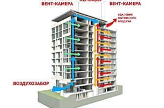
In a mechanical ventilation system, a duct fan is responsible for forcibly moving air through the ducts. The equipment is electrically powered and consists of a housing, a motor, and an impeller with blades.
According to their intended purpose, duct fans are usually divided into 3 types:
- Exhaust Duct equipment is designed to remove exhaust air from the room to the street.
- Supply Duct devices pump fresh air from the street into the room.
- Reversible Ducted equipment operates alternately for supply and exhaust. The coolers are equipped with a universal impeller, whose blades move air back and forth within the duct when the automatic system switches the direction of rotation of the motor rotor.
To simplify the installation of duct fans in air ducts, manufacturers have developed models with a housing of a corresponding cross-section. Based on their design, the equipment is divided into three types:
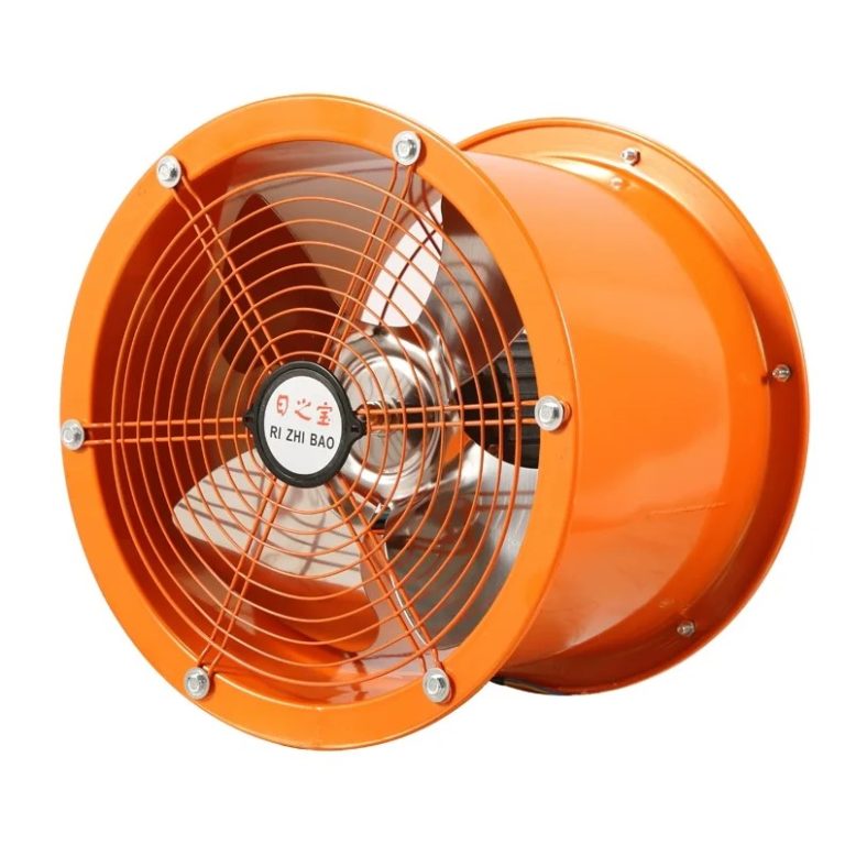
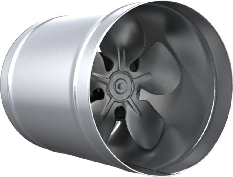
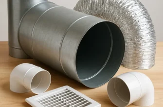
- Round models are designed for installation in cylindrical ducts. These devices are convenient for connection to corrugated pipes.
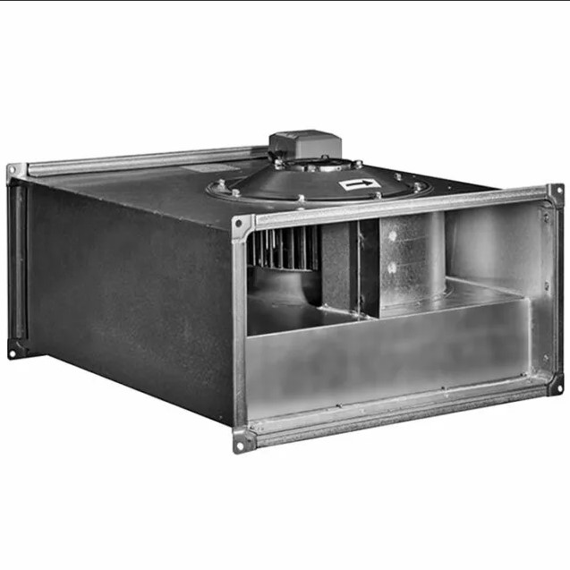
- Rectangular models are designed for connection to rectangular air ducts. This ventilation system is ideal for residential buildings where the ductwork needs to be concealed under suspended ceilings and other finishes.
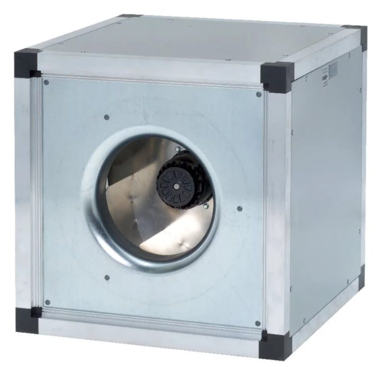
- Square-section models are designed for connection to square-shaped ventilation ducts. This bulky equipment is rarely used in residential buildings. This ventilation system is suitable for industrial and agricultural applications. Square ducts are occasionally found in basements and attics of older apartment buildings.
Theoretically, it's possible to connect a duct fan to a duct of a different cross-section using an adapter. In practice, the equipment is carefully selected to match the shape and size of the ventilation duct.
Matching the parameters of the cooler and the air duct is necessary for aesthetics, achieving performance indicators, and simplifying installation.
According to their design, there are 4 groups of duct fans:
- Axial models are made of a cylinderThe motor is located inside the housing. The impeller, mounted on the rotor, rotates around the central axis. The equipment is characterized by quiet operation, with noise levels below 50 dB. The operating pressure is limited to 700 Pa.
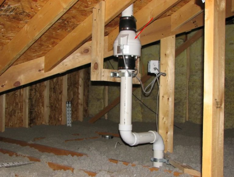
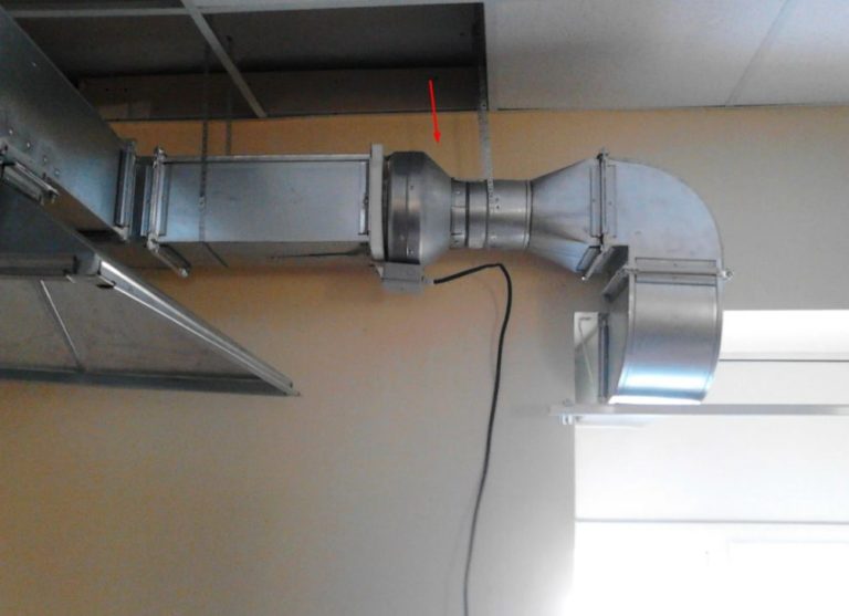
Axial coolers are popular for home ventilation. Larger models are connected to air ducts using corrugated hoses secured with clamps. The unit's frame is secured to a wall, ceiling, or other sturdy surface.
Models with a flange connection are available. The compact axial fan is inserted into a round duct at the edge or between the junction of two pipes.
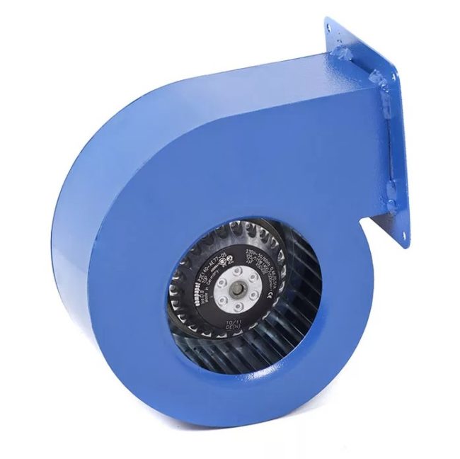
- Radial models feature a volute-shaped housing. The ventilation duct is connected via a bolted flange. The working components are located on a frame, which requires fixing to a supporting base. The rotor shaft with the impeller inserted into the volute housing. The rotating blades do not move air along the axis.
The flow is directed radially toward the impeller's periphery and is rejected by centrifugal force. Models with backward-facing impeller blades are characterized by lower noise levels, energy consumption, and power output.
Fans with forward-facing impeller blades offer higher performance. Duct fans are divided into three types based on operating pressure: low – up to 1000 Pa, medium – up to 3000 Pa, and high – up to 12000 Pa.
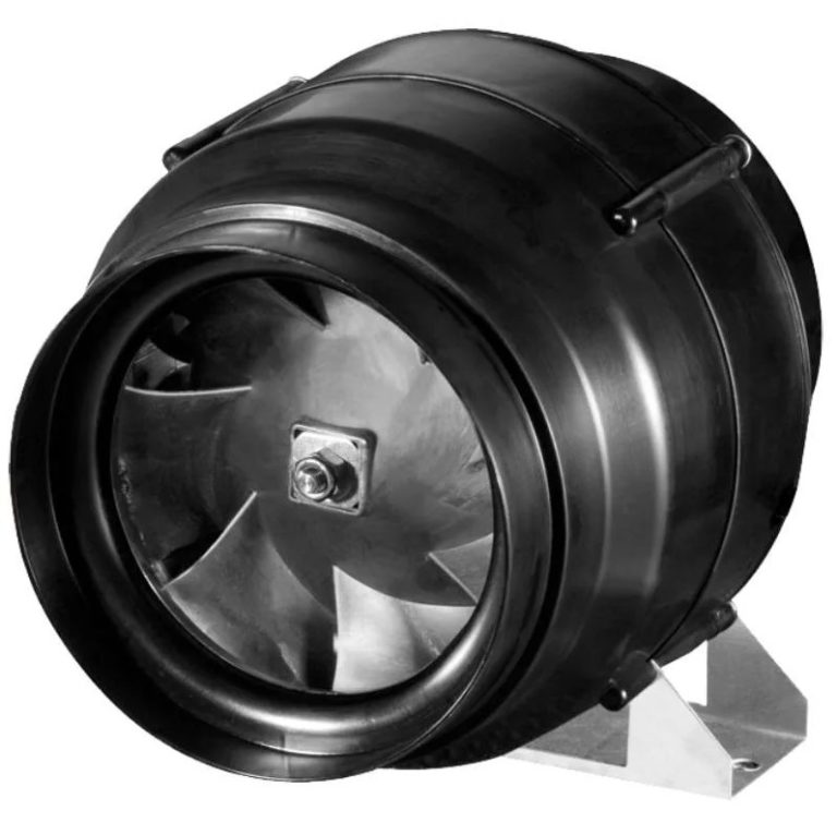
- Diagonal models are a combination of radial and axial coolers. Airflow within the case begins axially and then switches to radial.
The working pressure is generated in a chamber with rotating impeller blades, where the air flows. Ducted diagonal fans operate quietly and offer high performance, but are rarely used in domestic applications. Installation of these devices is particularly suitable for industrial ventilation systems.
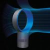
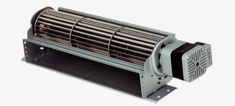
- Duct diametrical fans are called tangential fans. The impeller is a drum-shaped wheel. The housing inlet is equipped with a pipe for connection to the system. A diffuser is provided at the outlet.
Passing air through the impeller twice increases the cooler's efficiency, but at the expense of pressure and power. It's not common practice to install diametrically opposed equipment in ventilation systems. These devices are used in heaters, air curtains, and other climate control equipment.
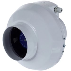
Centrifugal coolers are often considered the fifth type of duct cooler, but their operating principle places them in the radial group. An air flow is generated and pressure is subsequently increased by centrifugal forces generated by rotating blades along a specific trajectory.
Centrifugal fans are compact and quiet, ideal for connecting to home ventilation ducts. Connection to the ducts is made using a corrugated pipe and a clamp on the outlet.
Tools and materials for cooler installation
Installing a duct fan begins with preparing the materials. The first step is to select a duct fan based on its capacity. Calculate using the formula L = S × h × k. Substitute the following values for the letters:
- S – area of the room (m2);
- h – height from floor to ceiling;
- k – tabular value of air exchange rate.
According to sanitary standards, the value of k is set for each room taking into account its intended purpose.

Select a fan with a nozzle size and shape that matches the cross-section of the air ducts for easy connection to the ventilation system. The list of additional materials depends on the type of equipment being installed. You may need flange bolts or pipe clamps, ventilation duct sealant, corrugated pipe or duct fittings, and anchors.
Household coolers operate on 12 and 24 volts of direct current. Industrial and public utility equipment requires a 380 or 220 volt power supply. In apartments and private homes, household models are more common.
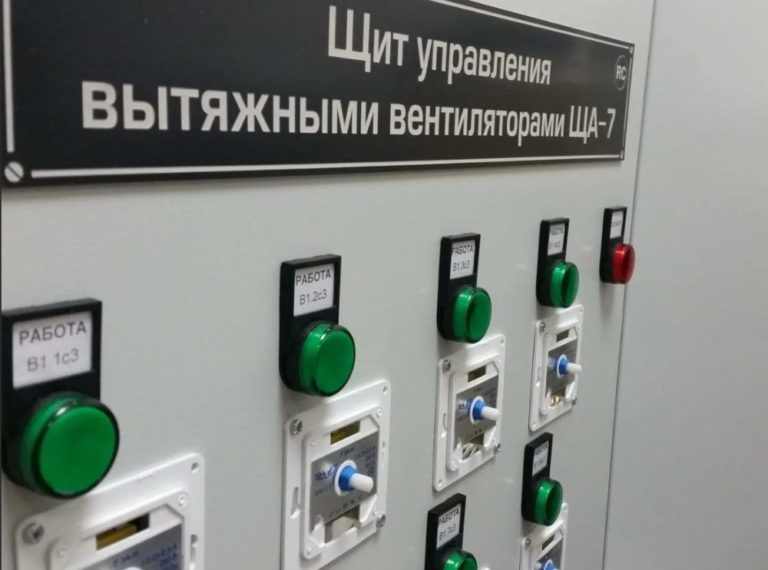
Connecting the devices to the power grid requires wiring. It's best to route the wires from all the fans to an electrical panel with circuit breakers or an electronic control unit. The panel's configuration depends on the chosen ventilation control system—manual or automatic.
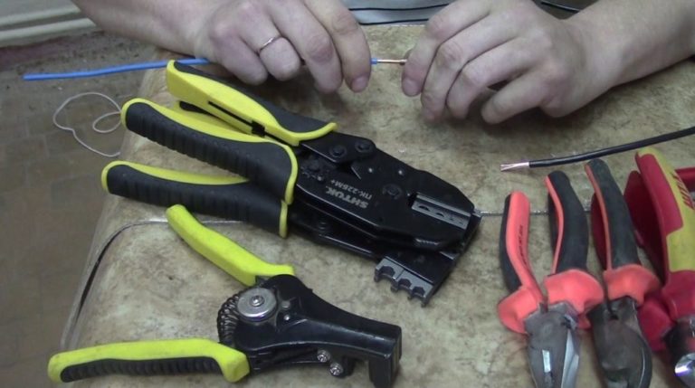
The following tools will be needed:
- Electric drill with a set of drill bits.
- Set of keys.
- Screwdriver with straight and shaped tip.
- Pliers.
- Bulgarian.
- Wire continuity tester.
- Indicator screwdriver for phase determination.
- Insulating tape.
- Pliers for stripping wire insulation and crimping terminals.
- Tape measure, pencil or marker.
You can add to or reduce the list of tools depending on the specifics of the work.
Choosing a location to install the cooler
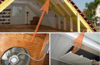
Choose a location for installing the duct fan that is accessible for maintenance. If you plan to conceal the equipment under the finishing, provide access hatches.
Install common-house fans at the inlet and outlet of the ventilation system. Use the attic, balcony, or utility room for installation.
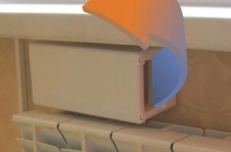
Place point-use devices in the air ducts that pass through rooms. Ducted exhaust fans should be located under the ceiling in the kitchen and bathroom. Place air handling units in living areas—bedrooms, living rooms, and hallways.
Fan connection diagram in the ventilation network
The electrical connection diagram for the electrical equipment is determined based on the schematic layout of the ventilation units. Spot coolers are often combined with home lighting. The main-house fan operates independently and can be manually controlled in the electrical panel.
Wiring diagram for the light switch
The circuit diagram for a low-power exhaust cooler is relevant bathroom, toilet And kitchenConnect the wires from the ducted unit parallel to the light bulb. When you enter the room and turn on the light switch, the range hood will also start. Ventilation will stop immediately after the light is turned off.
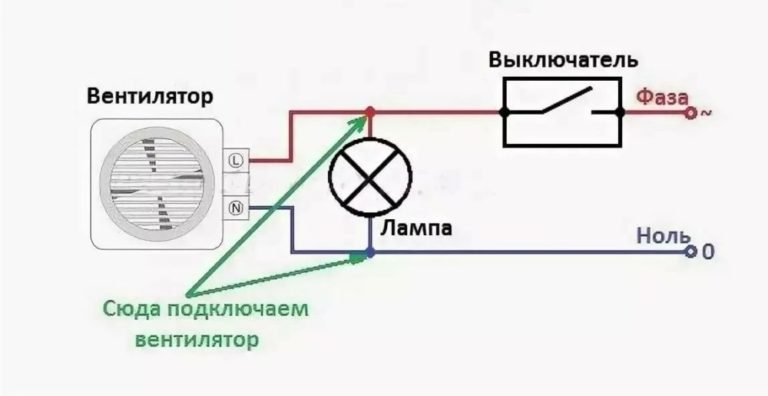
The advantage of the circuit is the ease of installation and the absence of the need to install a shield.
Disadvantage: the hood only works when the light is on.
Connection diagram via a separate switch
To ensure ventilation operates independently of room lighting, connect the equipment to a separate switch. It's inconvenient to control a ducted household fan from the control panel when the hood is only intended to operate briefly while people are in the room.
The solution is to install a two-button switch at the entrance to the room. One button controls the lighting, the other controls the ventilation.
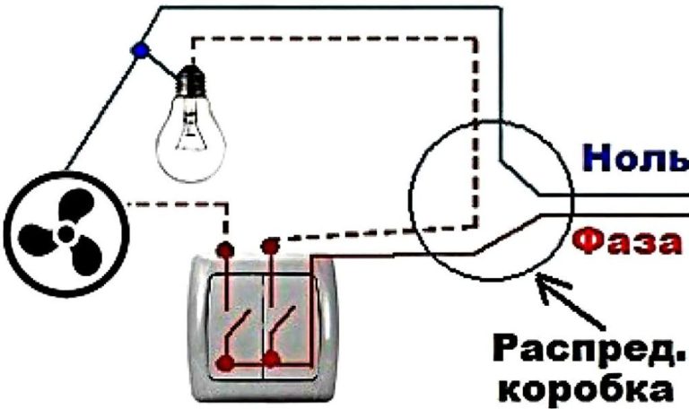
In the diagram, run the neutral wire directly to the light bulb and ventilation equipment. Connect the live wire to the common terminal, usually located at the bottom of the switch. From the corresponding terminals of each key, usually located at the top, run the live wires to the duct cooler and light bulb.
The advantage of the scheme is the ability to control the operation of the hood regardless of lighting.
The disadvantage is the inability to connect high-power common-house equipment. The light switch is not designed for high loads.
Wiring diagram with timer
A timer helps automate the operation of a domestic ducted water cooler. Use a single-key switch in the circuit, one for controlling both the lighting and ventilation. Connect the light bulb and the water cooler in parallel to the power supply. Use the switch to interrupt the circuit at the phase.
Run the third green wire to ground and connect it to the appropriately marked terminal on the ventilation unit. Connect the additional branch from the phase to the timer power supply. On the cooler, this terminal is marked "LT."
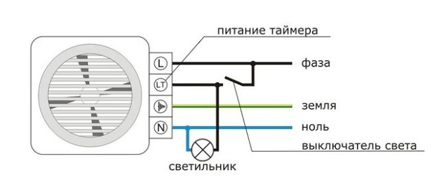
When you turn on the lights in the room, the ventilation will also start. After the lights go out, the ducted cooler will continue to run for the time set by the timer.
The advantage of this system is improved exhaust ventilation. The ventilation will continue to remove dirty air and moisture vapor after people leave the room and the lights are turned off. After a preset period of time, the ducted cooler will stop, saving energy.
The disadvantage of the scheme is that the ventilation operation depends on the lighting.
Wiring diagram with sensors
Air quality and humidity sensors help automate ventilation. In a simple setup, install the controllers in series with the cooler, breaking the circuit. Don't run power through the switch; instead, run the cable to a circuit breaker panel.
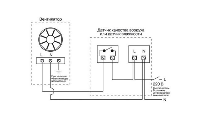
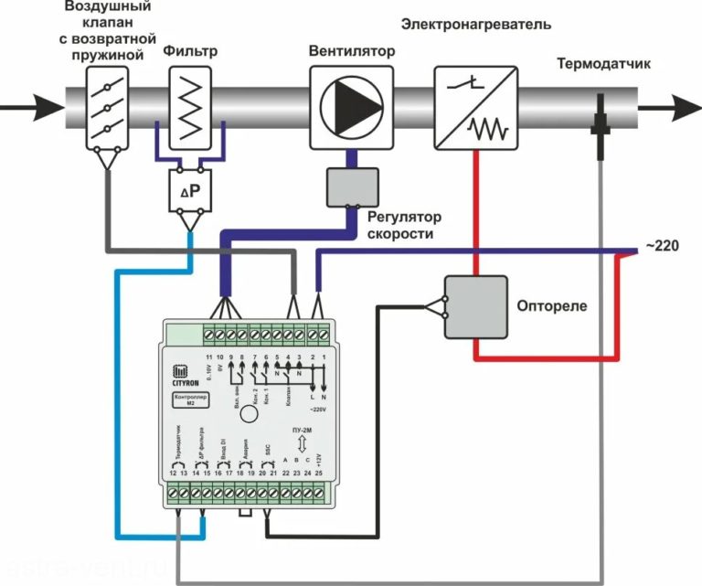
For a common-building ventilation system with automated controls, connect the sensors to the electronic unit. The connection diagram is provided by the equipment manufacturer. Place the control units in the electrical panel.
The advantage of the scheme is the autonomous operation of ventilation with climate control.
The disadvantage is the high cost and complexity of connecting the equipment.
Instructions for installing a fan in a square duct
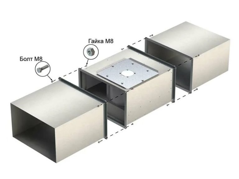
Connect the ventilation unit to rectangular air ducts using flanges or adapters. The choice of technology depends on the type of equipment being installed.
- If the fan and duct cross-sections are equal, use a flange connection. Place flexible gaskets between the joints and apply sealant. Tighten the flanges with bolts through aligned holes. Tighten adjacent nuts crosswise to ensure uniform tightening.
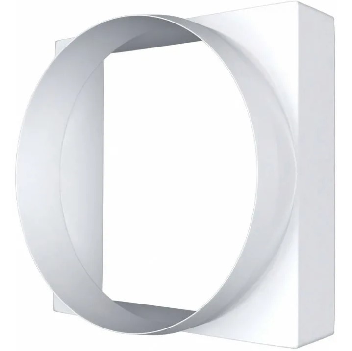
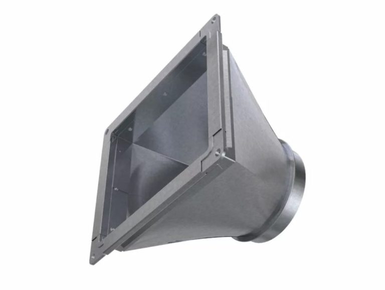
- Connect a round ventilation unit to a square air duct using a shaped adapter. The length of the adapter should be half the length of the cooler.
The adapter's inlet opening must match the cooler's impeller diameter. Ventilation equipment manufacturers specify this size in decimeters.
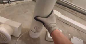
Instructions for installing a fan in a round air duct
It's easier to install a round cooler in an air duct of the appropriate cross-section. Choose the installation method depending on the type of equipment used:
- For bolted connections, the cooler and air duct connections must be equipped with flanges with aligned holes. Tighten the parts with bolts and nuts in a crisscross pattern to prevent distortion. To seal the joint, place an elastic gasket between the flanges.
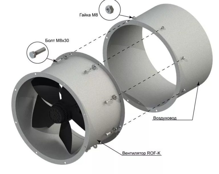
- When the ventilation unit's housing is large and the cross-section of the ductwork matches the diameter of the rigid ductwork, use a clamp connection. Secure the unit's base with anchors to the wall, ceiling, or other supporting structure. Attach the pipe to the fan ductwork. Use sealant to seal the joints. Secure the connections with clamps and bolts.
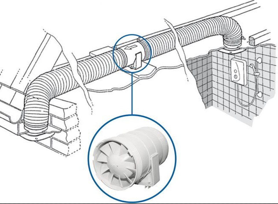
- If the ventilation equipment needs to be installed offset from the duct line or the pipe diameters don't match, consider a clamp connection using a corrugated sleeve. Secure the base of the unit to the supporting structure with anchors.
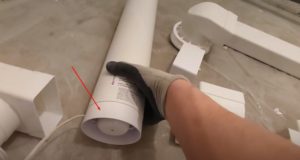
Install the removable motor housing with impeller onto the frame with the adapter pipes and secure with clamps. Connect the power cable or do it later. Connect the corrugated pipe sections to the pipes and secure with clamps.
Attach the other ends of the corrugated pipe to the cylindrical air ducts. Secure the connections with clamps in the same manner. Apply sealant to the joints to ensure a tight seal.
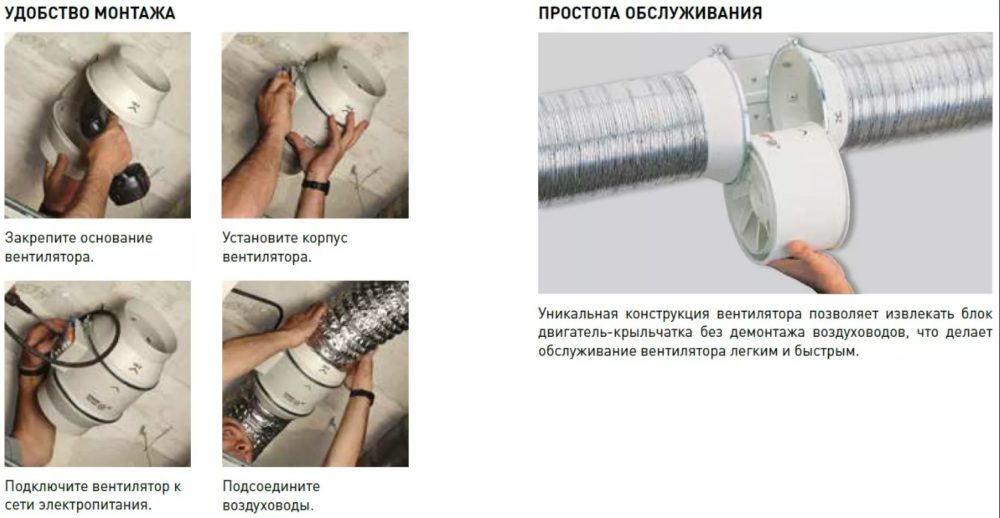
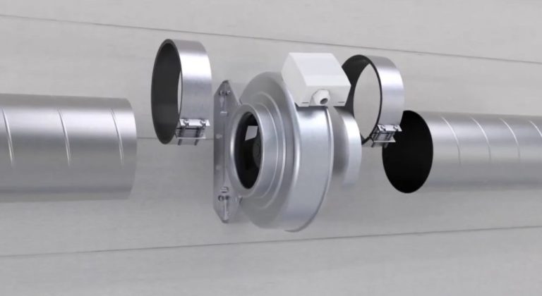
- Install the drop-in cooler by submerging the housing inside the air duct. Attach the pipes on both sides to the fan mounting point. In the diagram, the unit will be located at the junction of the two ducts. If you need to create a rectangular ventilation branch from the cylindrical air duct containing the cooler, first attach a shaped adapter of the appropriate cross-section to the housing mounting point.
Square ventilation equipment is rarely used in domestic ventilation, but it's worth considering connecting it to a round duct. For installation, use fittings with a smooth transition from square to cylindrical. The length of the adapter should be equal to or greater than ½ the length of the fan.
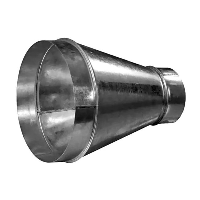
There are situations where the cylindrical air duct and the cooler outlet do not match in diameter. To connect, use a cone-shaped adapter. The cone opening angle is 8-10°.O.
Connecting equipment to the power grid
After installation is complete, connect the duct fan to the power supply according to the manufacturer's diagram. Determine which wire to connect to based on the terminal markings in the device's terminal box:
- L – phase;
- N – zero;
- LT – timer power supply phase;
- PE or a herringbone-shaped symbol made of strips of different lengths – grounding.
When connecting the wiring, de-energize the home network by turning off the circuit breakers in the electrical panel.
Install the power cable to the equipment installation location during the rough-in phase of the room's renovation. Use cable ducts so that a burnt cable can be replaced in the future without drilling into the wall or ceiling.
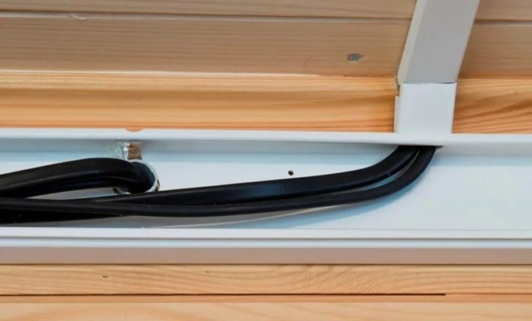
If you're installing ventilation in a finished room, try running the cable in a corrugated sleeve through the cut-out technical openings in the suspended ceiling. After installing the cable, conceal the perforations with putty or other material.
If you can't run cables under the suspended ceiling trim, temporarily install them in a cable channel near the ceiling molding. You can hide them under the trim later when you plan a new renovation.
Checking the cooler's functionality
After applying power, check the equipment's functionality. A properly connected, automatically functioning cooler is always powered in standby mode, as indicated by the indicator light on the housing.
According to the manufacturer's instructions, adjust the sensitivity of the presence and air quality sensor.
If you turn on the ventilation manually using the simple switch, pressing the switch will cause the rotor and blades to rotate. Make sure the impeller is moving the airflow in the correct direction. Press the switch again to turn off the power. The motor rotor will stop rotating.
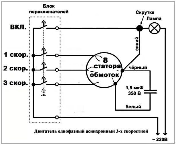
Features of installing a two-speed fan with a capacitor
For a multi-speed fan, install a separate switch with the appropriate number of positions. For example, consider the wiring diagram for a two-speed duct fan.
Connect the ground (PE) and neutral (N) wires to the correspondingly marked terminals without interruption. Connect the two phase wires, La and Lb, to the terminal of each switch. The speeds are switched alternately. Applying phase current to both La and Lb terminals simultaneously will burn out the motor winding.
Connect a three-speed cooler in the same way. Connect a phase wire to each phase terminal of the switch.
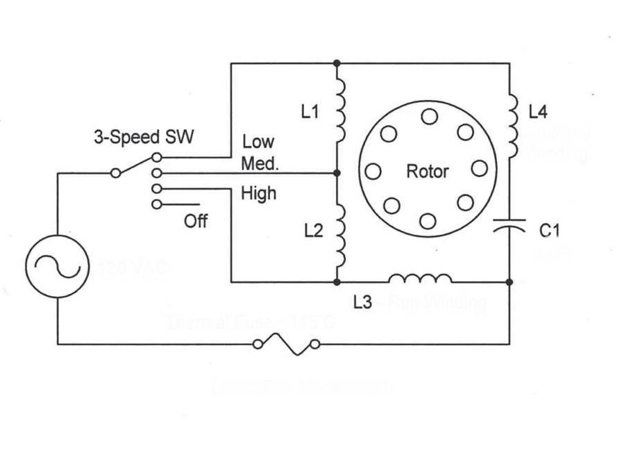
Connect a duct fan with a capacitor according to the diagrams discussed above. A component with a specific storage capacity is built into the equipment housing by the manufacturer. The capacitor is connected to the starting or operating windings.
Sometimes a combined connection is used. For the average user, the location of the capacitor and which windings it's connected to are irrelevant. Simply run the wires through the switch to the live and neutral terminals in the terminal box.
Answers to current questions
Install equipment in a location that's easy to maintain. Place the general-purpose ventilation unit in the attic or another designated area. Install spot exhaust units in the bathroom and kitchen. Place air handling units in living areas.
There's no difference. The term "duct" refers to the cooler's installation location—in the ventilation duct. The term "axial" refers to the design. The impeller inside the housing rotates along a central axis.
Rotating blades create a low-pressure area. Air is drawn into the housing, where it builds up to a higher pressure. The pressurized air is expelled through the outlet pipe and directed into the ventilation duct.
The electric motor's low protection rating against moisture and dust precludes outdoor installation. A protective structure against climatic factors must be erected, but installation in an attic or indoors is preferable.
Select equipment according to the ventilation duct cross-section. Calculate the performance using the formula L = S × h × k. Replace the letters with: S is the room area (m2), h is the ceiling height, and k is the table value of the air exchange rate for a specific room. To automate operation, supplement the cooler connection diagram with sensors and an electronic unit.