To assemble an air recuperator yourself, you need: make a heat exchanger, place it in the housing and connect it with pipes to the ventilation ducts.
We'll discuss the types of heat recovery units and their operating principles in more detail in this article. We'll also explore the step-by-step process for constructing a unit with a heat exchanger using plates, sewer pipes, and aluminum tubes.
- Types of recuperators
- Rotary type recuperator
- Plate heat recovery unit
- Heat recovery unit with intermediate coolant
- Chamber recovery unit
- Tubular freon recuperator
- DIY PVC Pipe Heat Recovery Unit
- Assembly of a compact recuperator from aluminum tubes
- Assembly of a plate heat exchanger
- Operating tips
- Answers to frequently asked questions
- A video about the operating principles of a recuperator
Types of recuperators
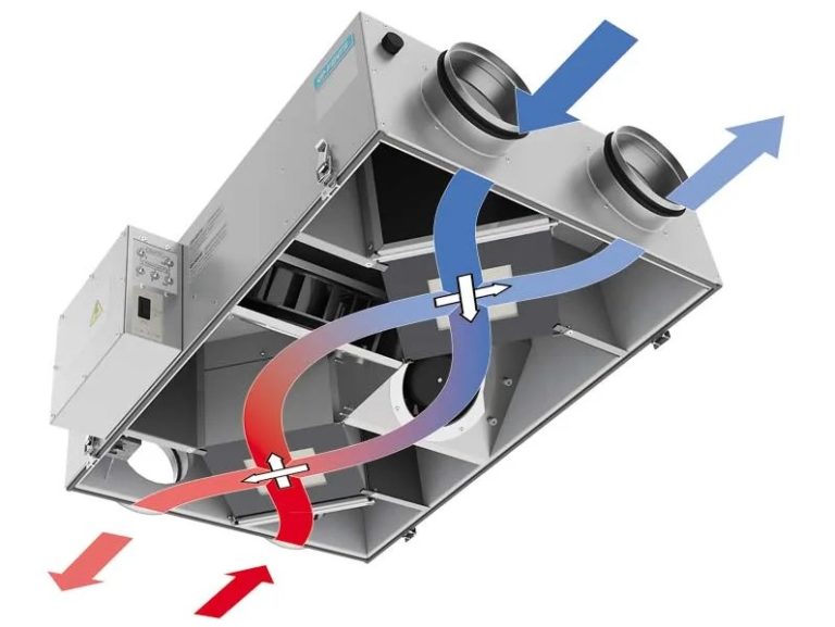
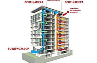
For increasing efficiency and reduction heat loss supply and exhaust ventilation It is equipped with a recuperator. In simple terms, the device is a structure consisting of one or two heat exchangers.
The incoming supply air from the street absorbs heat energy from the exhaust air flow from the room. A properly designed recuperator installed and configured saves up to 82% of power ventilation system and reduces heat loss up to 70%.
Thermal energy refers to both heat and cold. In winter, the incoming air is heated by the warm air exhausted from the room. In summer, the reverse process occurs when the air conditioner is running.
The supply air is cooled by the cold air exhausted from the room. In the first case, heating costs are reduced, while in the second, air conditioning costs are saved.
How recuperation occurs and what type of recuperator device is used is determined by the type of heat exchanger used.
Rotary type recuperator
While it's possible to build a rotary air recuperator yourself, it's not the best option for a private home or apartment. The heat exchanger is a rotor made of stacked plates. Space is left between each disk to capture and move air.
The rotating rotor passes through the exhaust air with one half of the vane wheel, absorbing thermal energy. Upon reaching the inflow zone, the heated discs release heat to the incoming air.
The other half of the wheel replaces the first half of the disk after one revolution. The rotor rotates in segments, one after the other, through the air intake and exhaust zones.
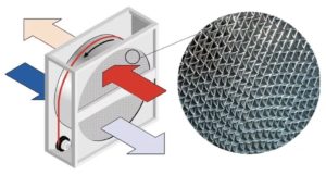
The rotary unit has one advantage: ease of assembly. Disadvantages include noisy operation, wear on rotating components, and contaminated air leaking from the exhaust air into the supply air.
The low recovery rate is 5%, which indicates that the labor costs of assembling a home ventilation device yourself are useless.
Plate heat recovery unit
The heat exchanger consists of a set of plates that create spaces for the flow of supply and exhaust air. The channels are arranged in an alternating pattern. The incoming air absorbs the thermal energy from the exhaust air, which is transferred to the walls of the contacting plate.
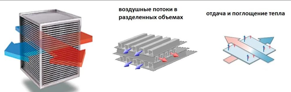
The plate heat exchanger is permanently installed and has no moving parts. Recovery is silent. Cross-point models offer recovery efficiency of up to 70%. Hexagonal units feature a combined counterflow design with a cross-point heat exchanger.

The recovery efficiency reaches up to 77%.
With its operational advantages and simple design, a plate heat exchanger for ventilation is cost-effective to assemble yourself. The device has no serious drawbacks.
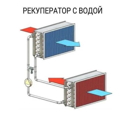
Heat recovery unit with intermediate coolant
The device consists of two heat exchangers. One unit is installed in the air inlet, and the other in the air outlet. The heat exchangers are connected by a pipeline to a forced-circulation coolant (water, antifreeze, or other liquid). The system operates similarly to a radiator heating system:
The advantage of a heat recovery unit is the ability to create a separate heat recovery system. The distance between the supply and exhaust vents is unlimited. One unit can be located in the house and the other in the attic. The disadvantages include cost and installation complexity.
Financial costs increase with increasing pipeline length. Furthermore, heat loss increases along the main line. Complex piping layouts discourage apartment and homeowners from building their own ventilation units.
Chamber recovery unit
The recuperator's heat exchanger is a metal chamber, whose walls transfer thermal energy to the air. The air flows along a trajectory determined by the damper. In the damper's first position, warm exhaust air warms one part of the chamber, while the other is filled with cold incoming air.
The damper, when switched to the second position, directs the cold inflow air to the first section of the chamber with warm walls for heating. The other, cooled section of the chamber opens to be heated by new exhaust air flows. The cycle repeats continuously.

The simplicity of the design is considered an advantage. A home or apartment owner can build a recuperator themselves. The recovery rate reaches 80%. Disadvantages include the presence of a moving damper, which creates noise.
Tubular freon recuperator
The heat exchanger operates similarly to a refrigerator or air conditioner. The tubular heat exchanger is filled with freon, which acts as a coolant. The exhaust air flow hits the bottom of the tubes, where the refrigerant condenses.
Absorbing thermal energy, liquid freon boils and rises. The influx hits the top of the tubes. The air absorbs the thermal energy. The cooled refrigerant condenses and flows to the bottom of the tubes. The cycle repeats constantly.
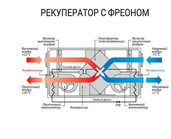
Assembling a tubular air recuperator with your own hands and filling the system with freon is difficult without experience working with refrigeration equipment.
The design is expensive and requires periodic maintenance, which is one of the main disadvantages.
The advantage is the ability to obtain the required recovery coefficient by adjusting operating modes.
DIY PVC Pipe Heat Recovery Unit
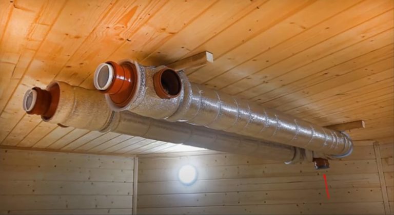
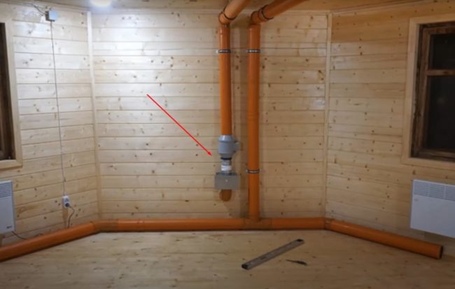
Of the five types of ventilation units, a chamber coaxial air recuperator is the easiest to assemble yourself. This design is considered the most reliable and efficient. To understand the recuperator's layout and operating principle, review the drawing of the overall ventilation system with the unit installed.
Now that the general idea is clear, let's take a step-by-step look at how to assemble a coaxial heat exchanger from a sewer pipe yourself:
- We begin assembly by preparing the materials. For the casing, you'll need two 160mm diameter PVC pipes, each 2 meters long. For the fittings, prepare two 160x110mm adapters, three 160x110x160mm tees, two 160mm elbows, and one 160mm coupling. For the internal duct, you'll need three 100mm diameter aluminum corrugated pipes and couplings.
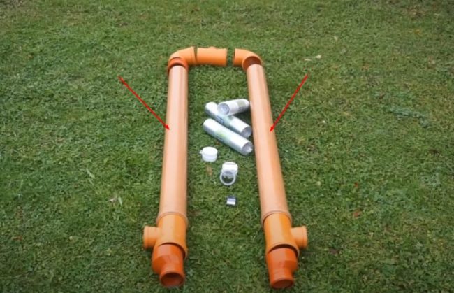
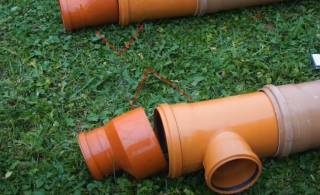
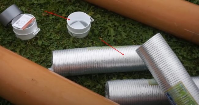
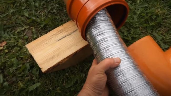
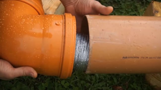
- Connect the tee to a 160x110 mm adapter. Make two such joints from fittings and attach them to one end of each PVC pipe. Leave the other two ends, where the casing will be looped, free. Extend the corrugated pipe to its full length. Connect the two aluminum pipes with the adapter. Leave the third corrugated pipe extended without connecting it.
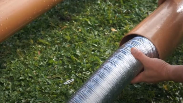
- Take the end of the pipe from the two connected corrugated tubes. Insert it into the PVC casing so that the end emerges from the 160x110 mm adapter hole.
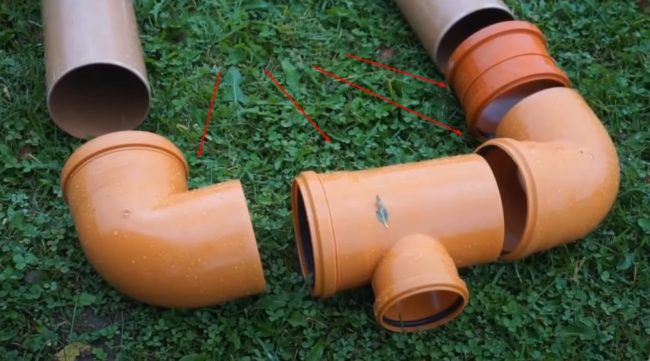
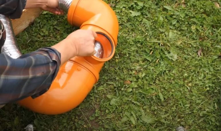
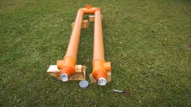
- Assemble a U-shaped casing loop assembly from two elbows and a tee. Insert the other end of the corrugated pipe into the resulting piece.
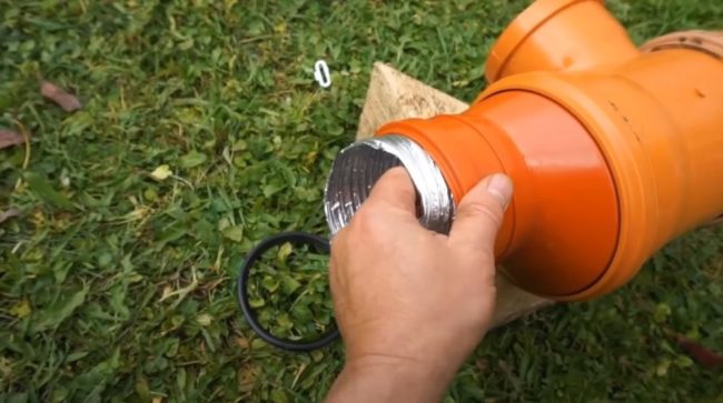
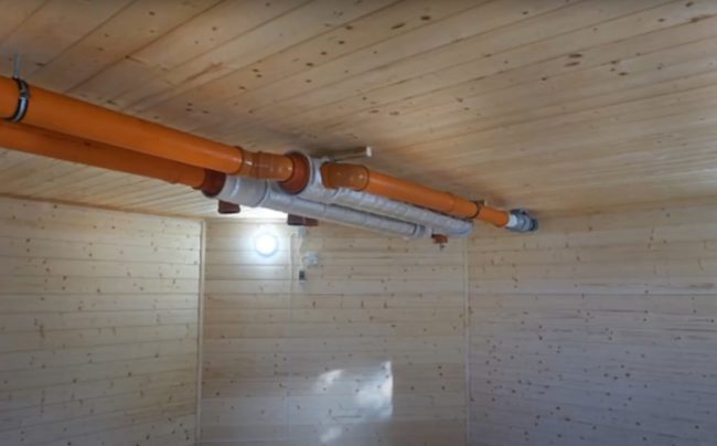
- Take the third straightened corrugated pipe. Insert the second PVC pipe inside, exiting through the 160x110 mm adapter. Attach a coupling to the other side of the heat exchanger casing to connect it to the elbow of the loop assembly.
- Connect the free ends of the corrugated tubing coming from the second PVC pipe and the loop assembly using a transition piece. Proceed with assembling the casing. Connect the PVC pipes to the elbows of the loop assembly.
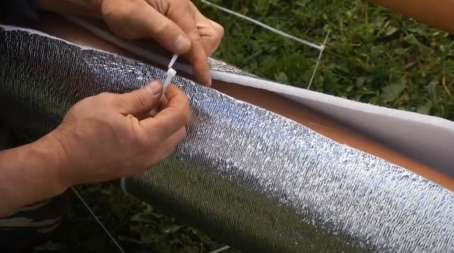
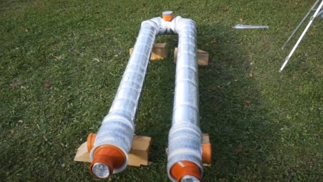
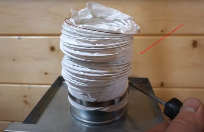
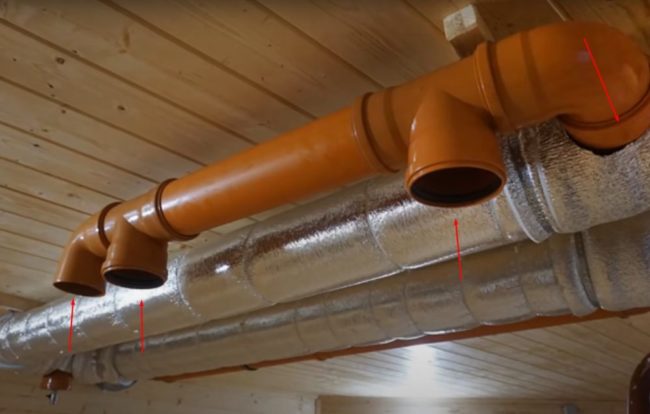
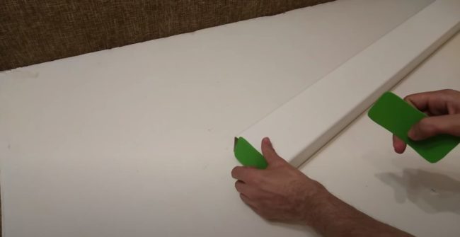
- To reduce heat loss, insulate the casing of your homemade heat exchanger. Wrap the pipes with foil-coated foam polyethylene. Secure the insulation with tape or plastic ties.
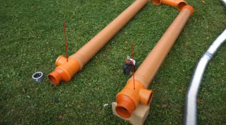
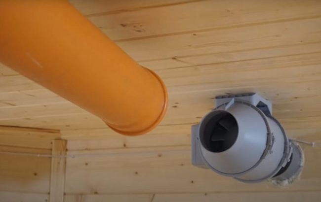
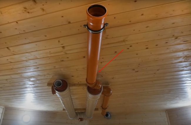
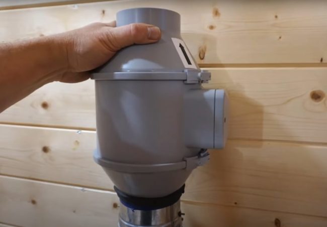
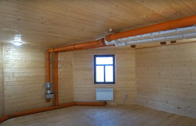
- Select a location to install your homemade heat recovery unit. In our example, we'll mount the unit on the ceiling. Close the tee on the loop with a plug and position it facing downward. This unit is used to drain condensate. For convenience, you can install a ball valve in the plug.
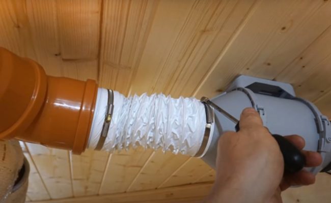
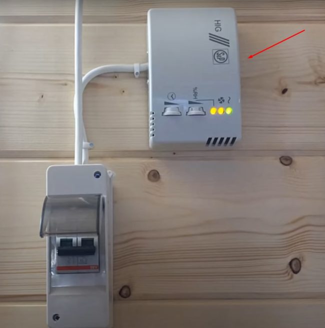
- According to the diagram, connect the exhaust and supply fans, filter, ducts, and other elements.
To test the efficiency of your homemade coaxial chamber heat exchanger, measure the outside air temperature and the incoming air temperature with a thermometer. If everything is done correctly, the incoming air flow will warm up to approximately 14°C after passing through the pipes.OC. The efficiency of a homemade ventilation system will be 78%.
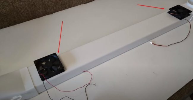
Assembly of a compact recuperator from aluminum tubes
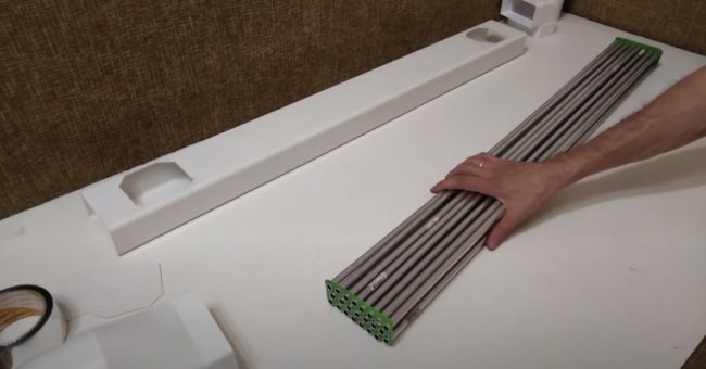
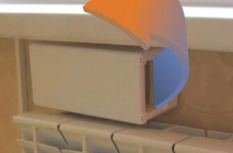
You can assemble a compact heat recovery unit yourself, similar to a radiator, and attach it to your plastic balcony door. You'll need 25 aluminum tubes, each 10 mm in diameter and 1 meter long.
Make the enclosure from a rectangular plastic ventilation box. You'll also need plugs, elbows, 100mm diameter aluminum corrugated pipe, tape, and sealant.
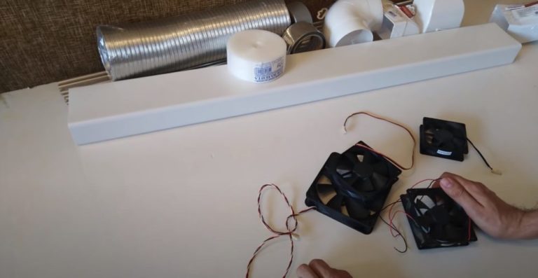
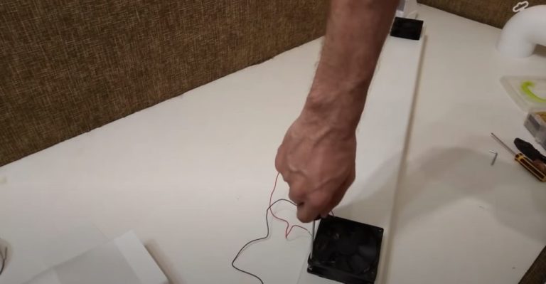
Computer coolers powered by a portable power supply will serve as the fans. The performance of this homemade setup is sufficient for a room of 12 m2.2.
Step-by-step DIY assembly instructions
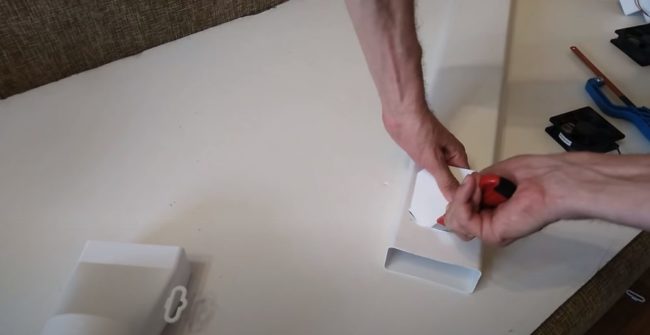
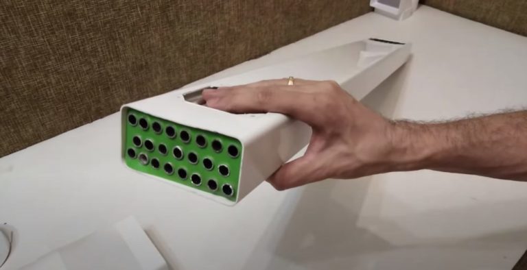
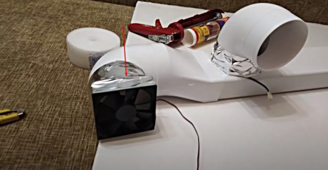
- To assemble the radiator, cut two end caps onto the rectangular plastic box. Mark 25 holes for the aluminum tubes in rows, evenly spaced. Make the slits with a utility knife.

- Mark two locations along the edges of the rectangular box for installing the coolers. Cut out the holes with a knife.
- Assemble the radiator core from aluminum tubes and perforated plugs. Insert each element into aligned holes to form a tubular block.
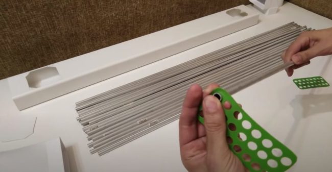
- Insert the resulting tubular block inside a rectangular plastic box.
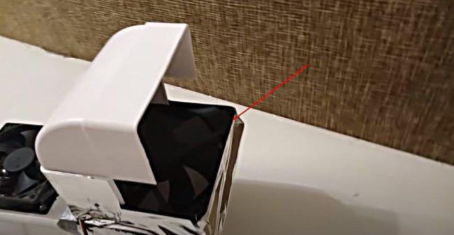
- Install the coolers on the box in the places where the holes were cut out and secure them with screws.
- Install shaped elements and 2 additional fans to create a supply and exhaust duct.
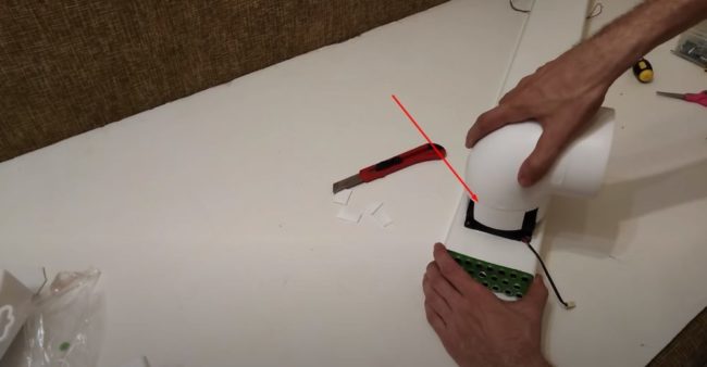
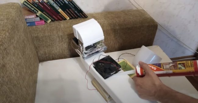
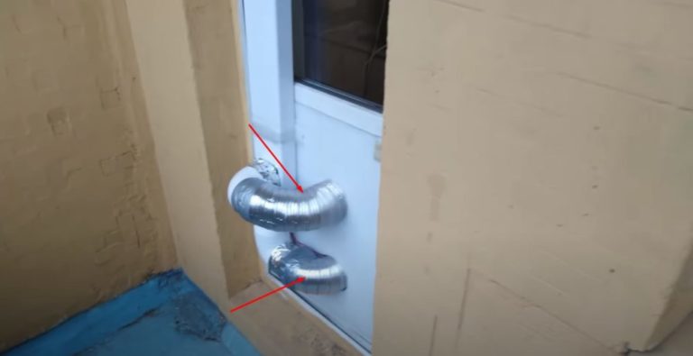
- Install the homemade heat recovery unit on the balcony door. Connect the ducts from the lower fans' outlets to the dampers cut into the door leaf using corrugated pipe. Attach the outlet pipe and filter fabric to the upper supply fan.
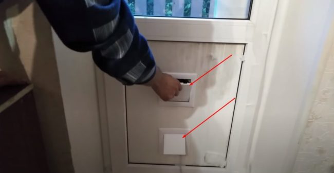

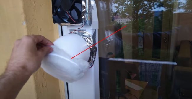
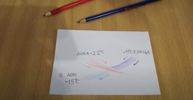
Connect the fans to the power supply, open the supply and exhaust hatches on the door, and check the efficiency of your homemade unit. In this example, the supply air entering through the heat exchanger is at a temperature of +11°C.OIt warms up to +15OC, if inside the room it is +22OWITH.
Assembly of a plate heat exchanger
To assemble a plate heat exchanger yourself, you'll need aluminum foil. Make spacers between the sheets using self-adhesive strips of rubber sealant. A galvanized box with four holes for the air ducts will serve as the heat exchanger's housing.
Let's start assembling it ourselves
- Cut a chipboard template to the dimensions of the future heat exchanger body for cutting the heat exchanger plates. Place the template on an aluminum sheet and trim with a knife. Cut the required number of plates in the same manner. The more layers you use on the heat exchanger, the higher the performance.
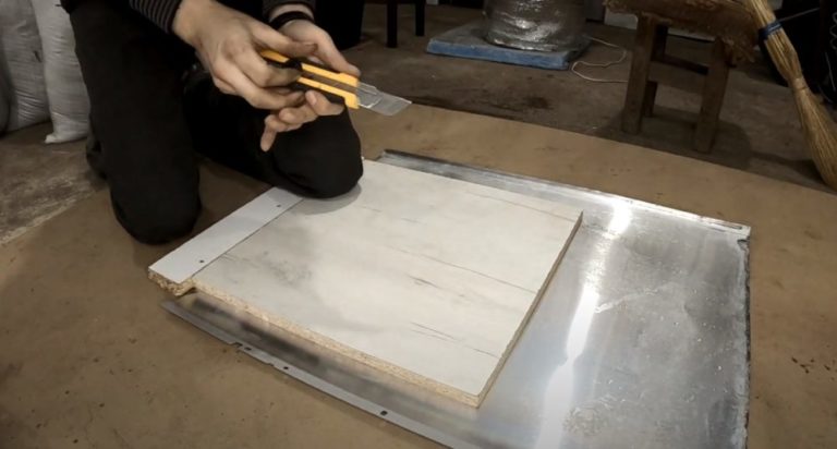
- Cut four aluminum corners to the height of the heat recovery unit housing. Secure the pieces to the corners of the chipboard template with screws. This will create a temporary frame for the heat exchanger housing.
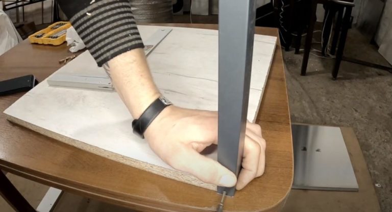
- Attach a self-adhesive door seal to each aluminum sheet along the two opposite edges and the center. Place the sheets between the cut corners to ensure that the glued crossbars in adjacent rows do not overlap. Channels with clearances should be created between the sheets, each on its own side of the square heat exchanger. For example, place even-numbered rows on the supply air side, and odd-numbered rows on the exhaust air side.
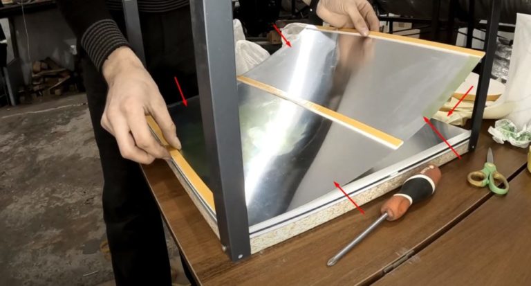
- Remove the assembled plate heat exchanger from the temporary frame. Apply an additional layer of adhesive to the corners and center of the plate structure where the bonded crossbars are attached for sealing.
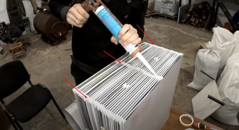
Install the plate heat exchanger inside the housing. Ensure the channels are correctly positioned relative to the inlet and outlet ports.
Operating tips
Insulate your homemade heat recovery unit and ducts to reduce heat loss. Regularly check the fans for proper operation, clean the ducts and vents of dirt, and replace or clean the air filters.
To increase power, install higher-performance fans. A speed controller allows you to select a comfortable operating mode.
Answers to frequently asked questions
The unit should be installed in a location away from the bedroom and children's room. Suitable locations include an attic, basement, balcony, or separate room.
The indicator depends on the model. Domestic units are designed for rooms up to 40 m2, and less commonly, up to 100 m2.
The price of a power supply unit depends on its power and model. The average price ranges from 30,000 to 100,000 rubles.
Standard installation costs range from 5,000 to 7,000 rubles. Custom installations charge between 200 and 3,000 rubles for each additional step. Each company sets its own price list.
In mechanical ventilation, the recovery unit saves up to 82% of the system's power and reduces heat loss by up to 70%.