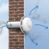
Are you installing ventilation but don't know how to install a roof penetration? A penetration is a shaped or homemade element that provides a sealed connection between the roof covering and the exhaust pipe exiting through a through-roof opening.
The ventilation system part is produced according to GOST-15150. A shaped unit made of plastic or galvanized rolled metal is designed to remove air at a temperature up to +80OC, humidity within 60%.
This article will detail the components of a roof ventilation penetration unit, its various components, and installation instructions. You'll also find recommendations for installation and operation, as well as answers to frequently asked questions.
- The structure and types of the passage unit
- Preparing the roof for installation of the passage unit
- Tools and materials
- Installation of rectangular penetrations on soft roofing
- Installation of rectangular penetrations on a roof made of corrugated sheets and metal tiles
- The nuances of installing penetrations on different types of roofs
- Recommendations for installation and operation of penetrations
- Answers to frequently asked questions
- Video materials
The structure and types of the passage unit
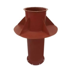
Previously, penetration assemblies were made of metal using a welding process. The design was based on a horizontal support platform with welded connections for connecting the ventilation riser from the interior of the building and extending the pipe from the outside.
Welded penetrations are now manufactured in custom sizes for installation on concrete roofs.
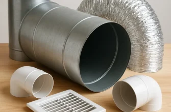
For modern roofs, manufacturers produce shaped penetration assemblies (PU) made of polymers or rolled metal with galvanized and decorative coatings to match the roofing design.
The design depends on the version. The outdoor chimney can be insulated or cold. The top is equipped with a protective cap/deflector. The base consists of a mounting flange, a sealing gasket, and a housing.
Depending on their design, the following types of passage units are distinguished:
- round, square, oval, rectangular;
- with valve and without valve;
- with valve and ring for collecting condensate;
- with manual and electric valve control;
- with a spark arrestor or a regular cap.
The manufacturer supplies the passage units with fasteners, seals, mounting hardware, and corrugated tubing. The exhaust air flow rate is determined by the pipe diameter. This diameter must match the cross-section of the ventilation riser exiting the building.
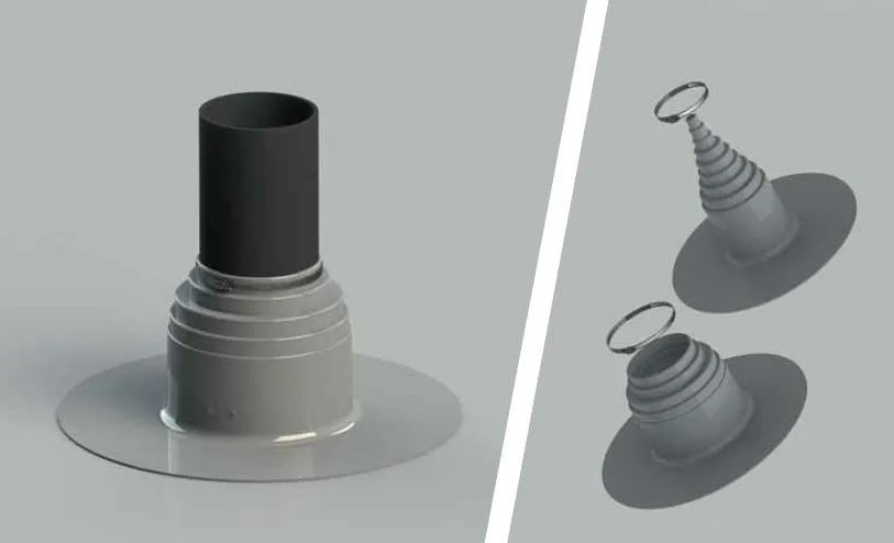
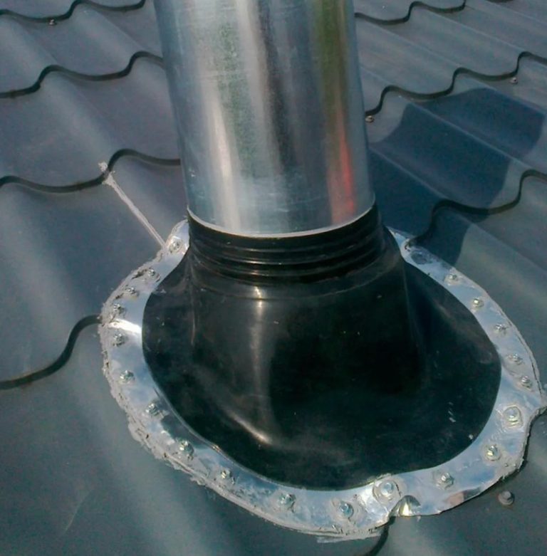
The universal joint is made of a pyramid-shaped rubber pad. The user cuts the top of the pyramid with a knife to fit the diameter of the pipe being installed. The elastic element is convenient for installation on soft roofing. Technonicol and relief corrugated sheet or metal tiles.
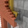
When a rectangular brick chimney or box with several insulated air ducts inside extends onto the roof, roofers construct the passage unit themselves using abutment strips.
The top of the structure is equipped with a canopy. Adjoining strips cover the gaps between the box and the edge of the cut roofing.
Preparing the roof for installation of the passage unit
The factory-assembled entry unit comes complete with components for quick installation. No additional purchases are required, except for sealant for the joints.
Choose a location for the air duct outlet as close to the ridge as possible to achieve better draft and reduce the height of the pipe on the roof. SNiP No. 41-01-2003, the top edge of the hood should rise above the highest point of the roof:
- flat roof – 30-50 cm;
- pitched roof – minimum 50 cm with the distance of the chimney from the ridge girder up to 1.5 m.
When on a pitched roof ventilation pipe If the pipe is located 1.5 to 3 meters away from the ridge purlin, position the top edge of the hood flush with the ridge. If the distance is greater than 3 meters, draw an imaginary line at a 10° angle to the ridge purlin to determine the height from the top edge of the pipe.O.
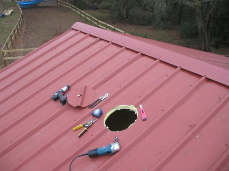
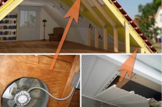
Choose a roof perforation location in a clear area where there are no rafters. Make a through hole in 2-3 cm larger than the dimensions of the pass-through element. The roofing cake cutting technology should be determined by the roofing material.
Cut a cross-shaped hole through the vapor barrier and insulation on the attic side with a knife and fold it aside. Mark the hole outline by drilling into the roofing material with an electric drill.
Cut out the section of the hard roofing itself with a jigsaw or metal shears from the street side. You can cut the section of the bitumen roofing with the wooden sheathing with a hacksaw.
Tools and materials
For installation, you'll need a jigsaw, drill, screwdriver, pliers, and a hacksaw. If you plan to bend the metal flashing, you'll need a mallet, metal shears, and a hand-held bending tool. Additionally, be prepared with a knife, tape measure, level, marker, or pencil.

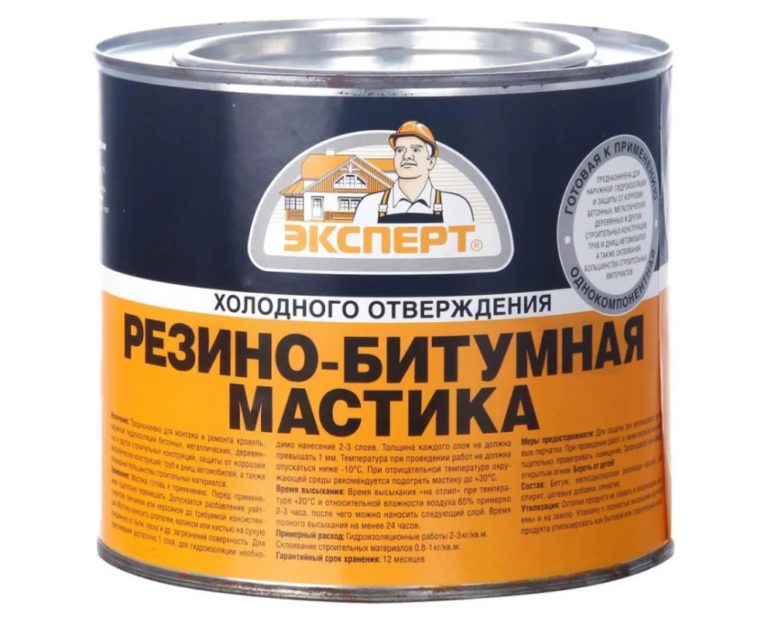
The materials you will need are the shaped element itself, bitumen mastic or sealant to seal the joints.
Installation of rectangular penetrations on soft roofing
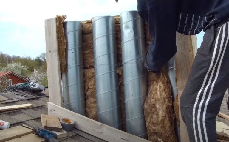
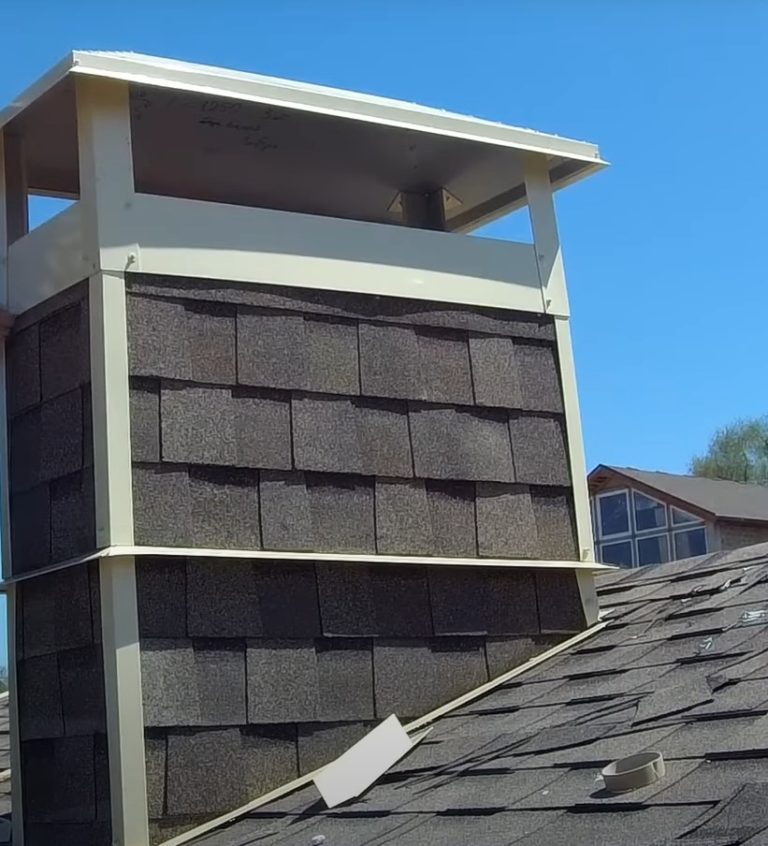
Homemade insulated rectangular penetration assemblies for soft roofing are made from a box made of slats. Ventilation pipes pass through the interior of the structure.
The free space of the box is filled with thermal insulation. Roofing material elements are used for the outer cladding. To protect against precipitation, the top of the penetration is covered with a canopy.
Let's take a closer look at how to practically install a rectangular ventilation passage unit through a roof made of flexible bituminous shingles.
- On the roof slope covered with flexible shingles, mark the location of the ventilation unit. To avoid damaging the rafter system when cutting out the rectangular roof section, drill a hole from the attic side to define the outline of the marking lines.
Using a drill, drill four holes at the corners of the future cutout. On the outside of the roof, use chalk to draw lines connecting the perforations.
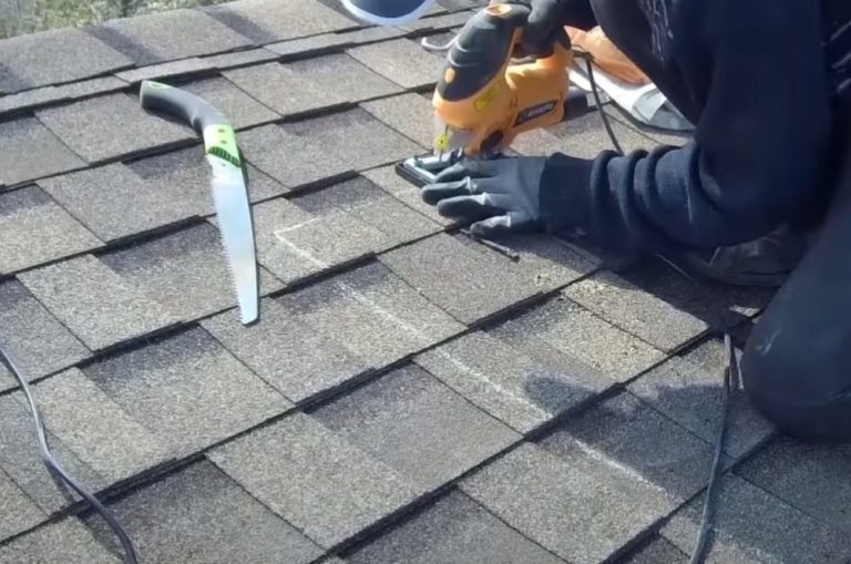
- Using a jigsaw, cut out the roofing section along the marking lines. Start cutting from the corner where the saw blade can be inserted into the marking hole. If the jigsaw is difficult to use on flat roof sections due to the thickness of the roofing material, cut the section by hand with a wood saw.
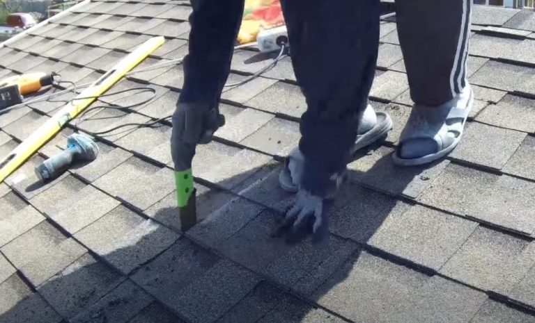
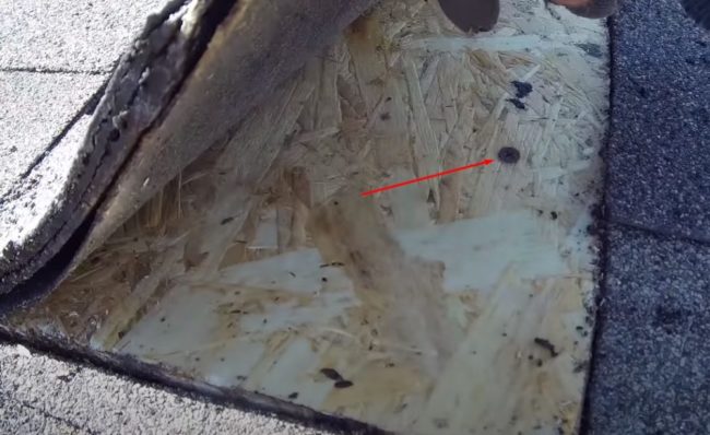
- Lift the shingles from the cut-out section of the roof. A section of the top solid OSB sheathing may be held in place by screws. Remove the fasteners with a screwdriver or drill. Remove the cut-out OSB section.
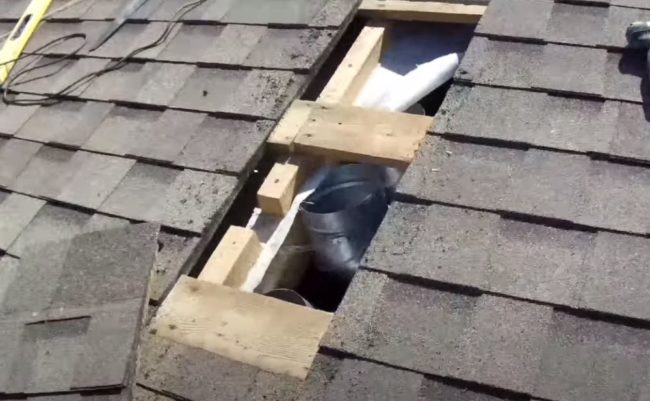
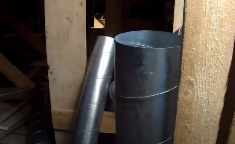
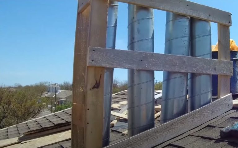
- Use wooden blocks to assemble the feedthrough box. Assemble the base in the attic. Extend the slatted posts above the roof level through the cut hole.
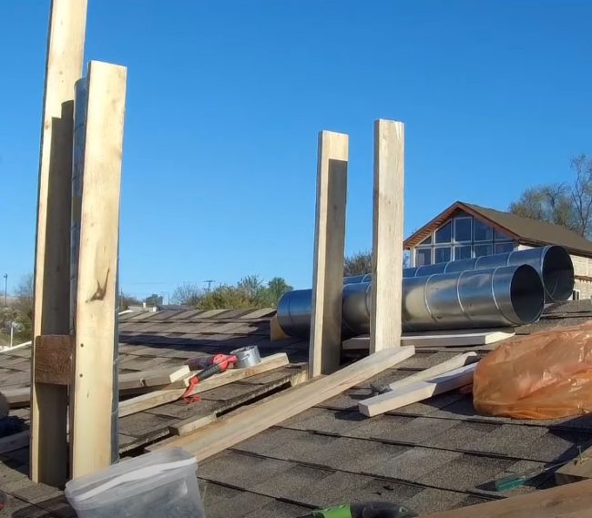
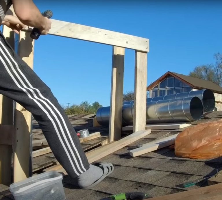
- Connect the street-facing posts of the walk-through unit with board crosspieces to form a rectangular box. There should be three rows of crosspieces: one on top of the vertically installed beams, one in the middle, and one at the bottom, flush with the shingles.
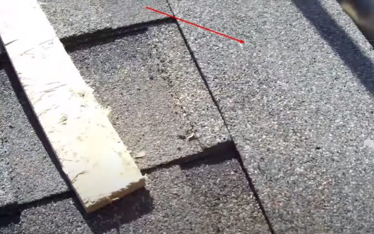
- Install the bottom lintels simultaneously with the first layer of sealant. Apply bitumen sealant along the edge of the cut shingle section. Glue on a flashing strip that matches the material and color of the main roofing material.
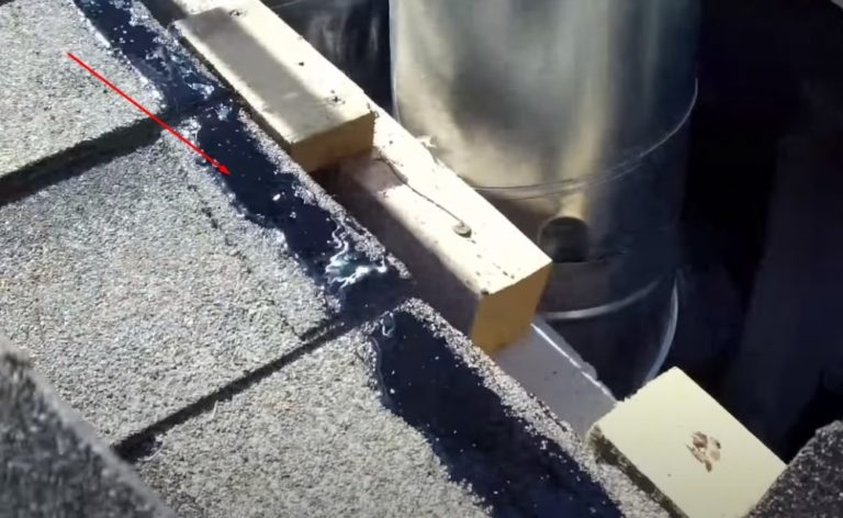
This piece will smooth out the differences in height created by the rows of asphalt shingles. Place the bottom header flush with the glued strip and secure it to the studs with screws.
- Extend the height of the ventilation ducts coming out of the attic. Use corrosion-resistant stainless steel pipes.
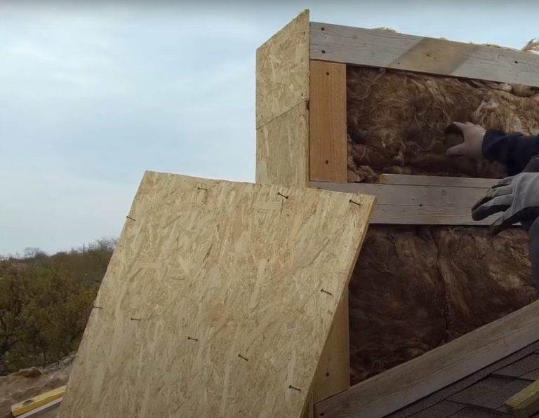
- Cover the frame on three sides with OSB panels. Temporarily secure the panels with a few screws. You may need to remove the sides to check the insulation's integrity.
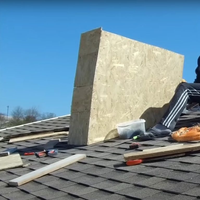
- The fourth side of the pass-through box remains open. Use this opening to install thermal insulation. Use pieces of mineral wool to tightly fill the space between the ventilation pipes and the inner walls of the box.
- Cover the fourth side of the box with a piece of OSB. Remove the sheathing from the other sides one by one, checking the density of the mineral wool. Fill any voids with insulation. Replace the sheathing and secure it securely with screws.
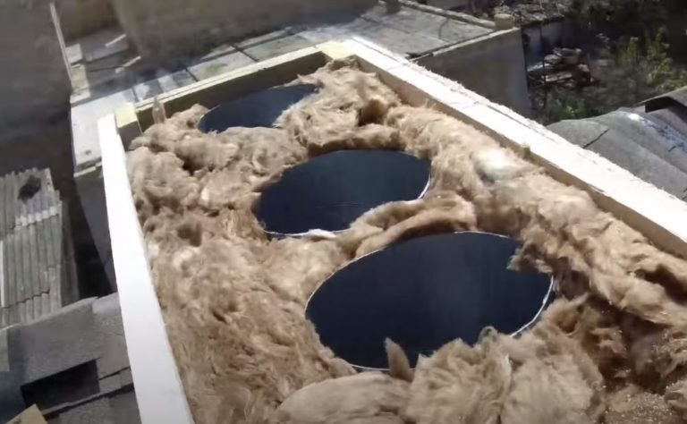
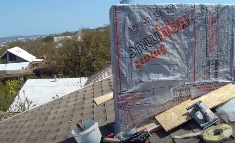
- To protect the mineral wool from condensation damage, cover the frame sheathing with a vapor barrier film. Attach the film with a folded edge to the main roofing. Any condensation will flow down the vapor barrier onto the bitumen shingles and be drained into the gutter system.
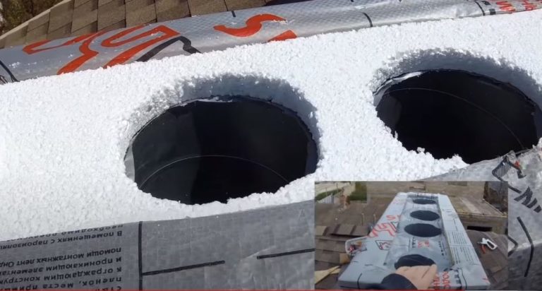
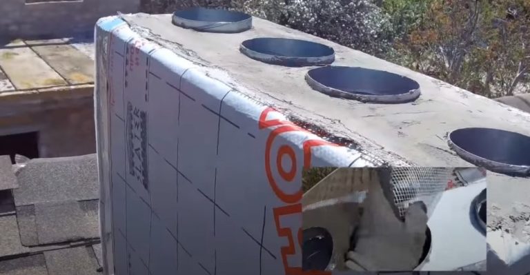
- Cover the mineral wool at the top of the entryway with a vapor barrier. Cut a strip of 30-50 mm thick foam plastic to fit inside the top of the box. Cut holes for the ventilation pipes.
Cover the end of the box with a piece of foam plastic, placing it on top of the vapor barrier. Create a finishing layer of reinforcing mesh and cement mix on top of the foam plastic sheet.
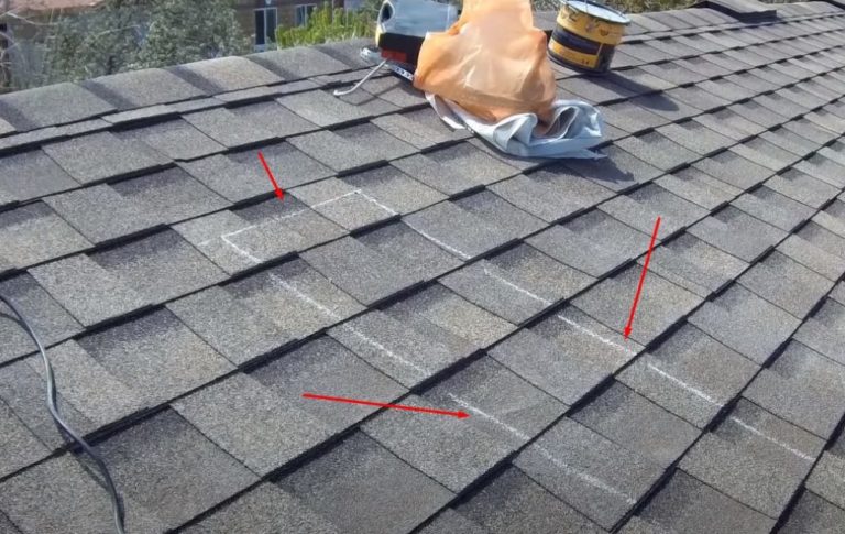
- Once the ventilation ductwork is installed, proceed to finishing. Attach flashing strips along the perimeter of the lower portion of the box. These will ensure a tight seal between the ductwork and the roof edge.
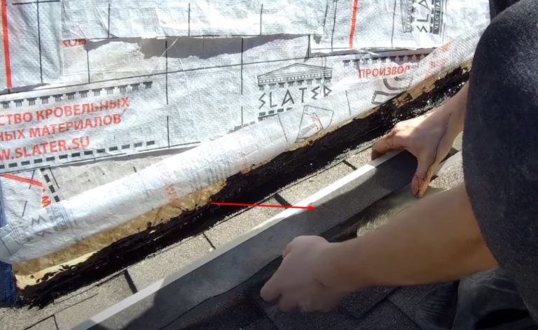
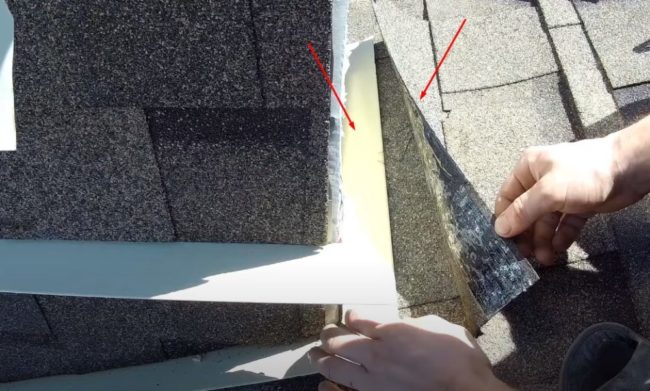
To properly install the flashing, first apply bitumen mastic to the edge of the shingle around the perimeter of the flashing. Cut a strip of flexible roofing material. Insert the piece into the groove on the back of the flashing.
Take some self-adhesive bitumen tape and cut it to the length of the flashing. Apply it to the fold of the flashing, creating a groove for the shingle strip to be inserted.
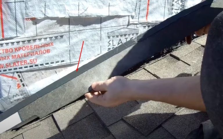
Glue the extension piece onto the bitumen mastic. Use screws to attach the strips only to the walls of the box, tucking the edge of the vapor barrier under.
- To cover the box, use the same material as the roofing material. In this case, it's flexible shingles. Nail the shingles to the box walls. Overlap the bottom of the vapor barrier and shingles onto the flashings and trim them to match the roof plane.
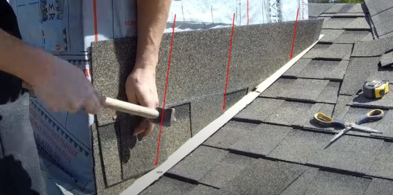
- Approximately in the middle of the box, secure the second row of abutment strips bent at an angle of 110 with self-tapping screws.OThe structure will act as an additional canopy.
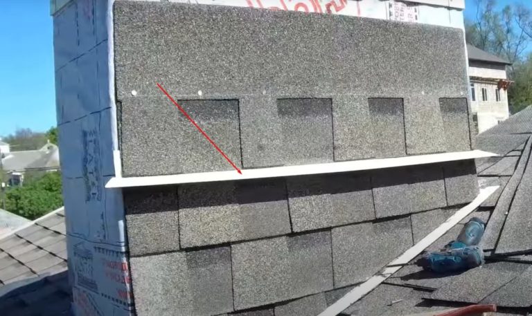
- To prevent water from seeping under the lower counter flashing from the ridge, cover the top of the flashing with an additional strip of flexible shingles. Glue the piece onto a thick layer of bitumen mastic. After sealing the joint, continue shingling the fourth plane of the box from the ridge side.
After covering the box, cover the corners with decorative metal strips. Install the main canopy on the roof penetration to protect the ventilation pipes from precipitation and debris. Secure the metal cap with screws.
Installation of rectangular penetrations on a roof made of corrugated sheets and metal tiles
On a roof made of metal tiles and corrugated sheets, installing a rectangular penetration unit follows the same principle. It's easier to use prefabricated extensions. Depending on the installation location, penetrations are manufactured in two different styles.
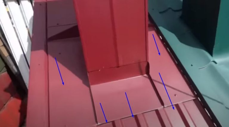
- The lower penetration is installed on the roof, where the ventilation outlet is located closer to the eaves. The rectangular ventilation pipe cladding elements are made with large-area bends. The penetration is cut under corrugated sheeting or metal roofing.
The lower element curves down the roof slope to the drainage system tray. Melt and rainwater that enters through the gaps under the roofing sheets is channeled into the drainage system.
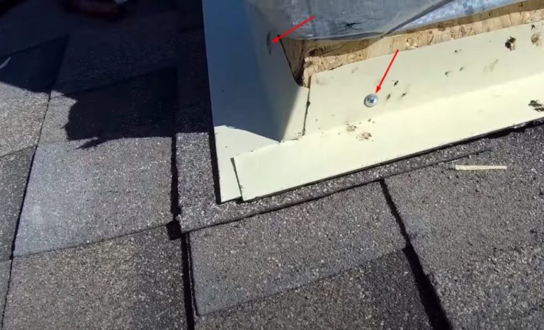
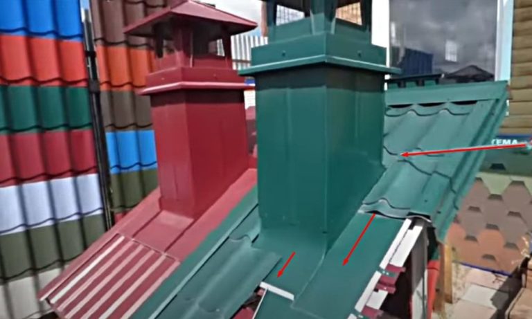
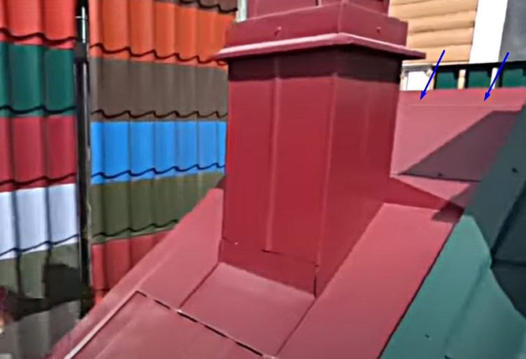
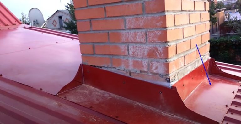
- The top penetration is installed on the roof, where the ventilation outlet is located closer to the ridge. The box with wide bends is not cut under corrugated sheets or metal tiles, but is attached above the roofing. Water flows from the two side flanges and the lower bend along the main roof surface into the drainage system channels.
The top bend of the box is tucked under the ridge cap. Water from the ridge drains over the top, spilling onto the side and bottom flanges. If the top bend isn't long enough to tuck under the ridge cap, the element is extended with a flat sheet of rolled metal matching the roof color.
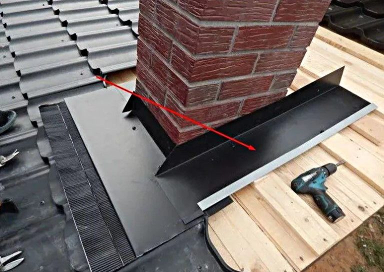
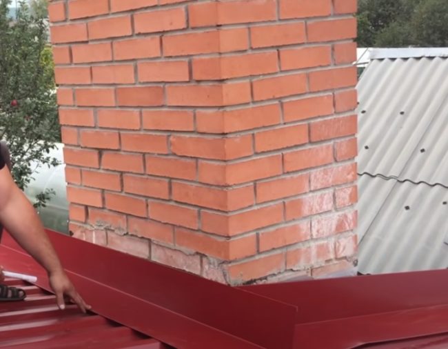
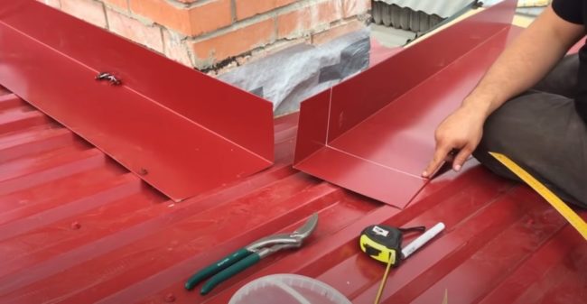
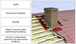
When making a rectangular ventilation pipe passage unit on your own, roofers make it from abutment strips.
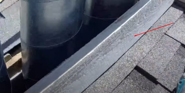
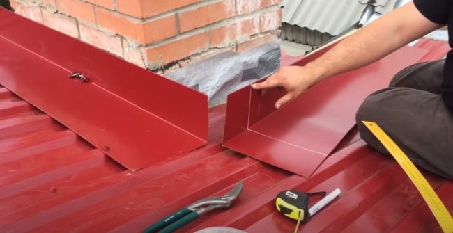
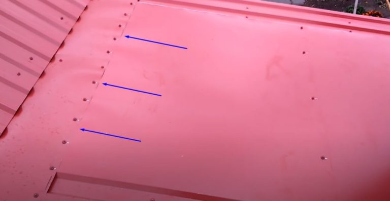
- Place flashing strips around the perimeter of the rectangular pipe over the metal roofing or corrugated sheeting. Mark the joints where they will be rolled. Temporarily secure the flashing to the roof purlin on the ridge purlin side with two screws.
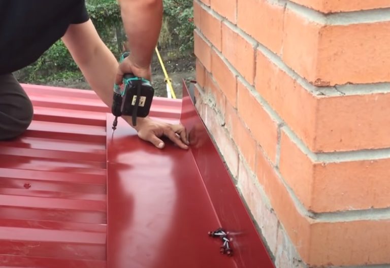
- Attach the side flashing strips to the vertical shelf of the attached flashing. Measure the gap at the top where the strips meet due to the slope of the roof. In this example, it was 15 mm.
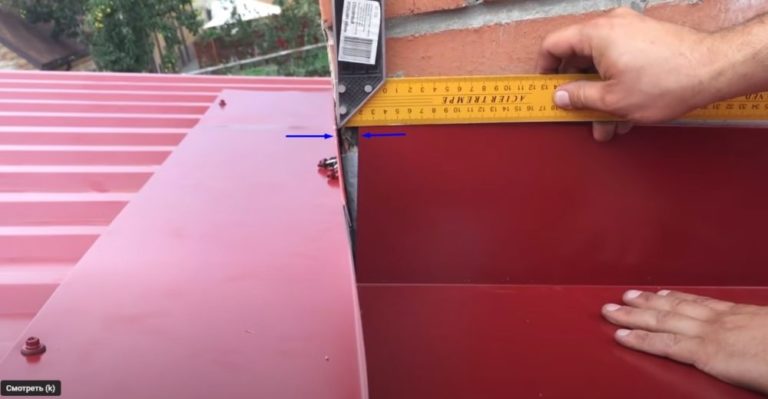
- To create tight corners at the rolled joints, mark the fold lines at the ends of the abutting strips. In this example, on the bottom shelf, the line runs 150 mm from the edge.
At the top of the vertical shelf, the indent from the edge is maintained taking into account the size of the previously measured gap, and is 135 mm.
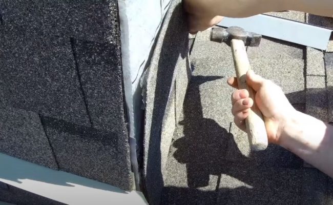
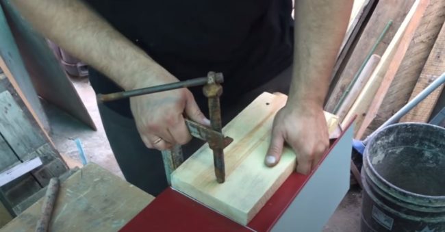
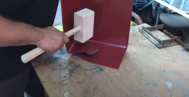
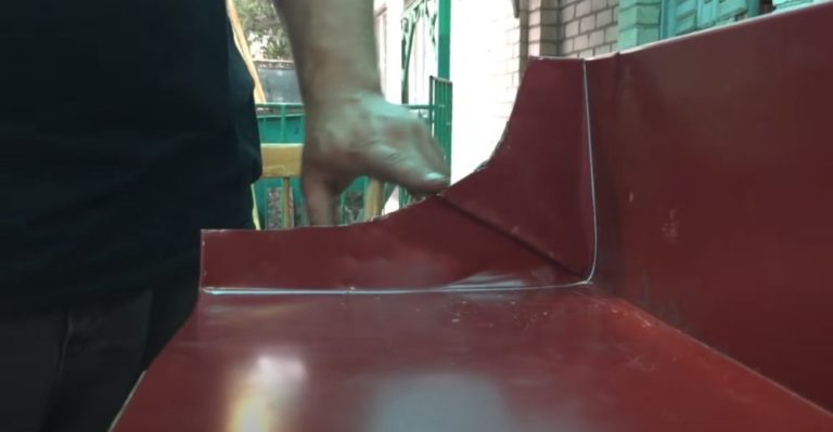
- Place two pieces of cut boards along the marking lines and clamp them together. Bend the shelf slightly along the markings. Remove the boards from the clamp. Using a mallet and a bending tool, form a blind corner without cutting any metal.
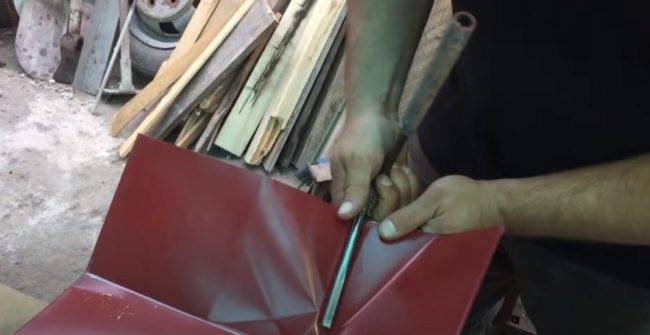
- On the resulting corner shelf, draw a diagonal marking line. Cut a piece of metal to create a section for rolling with a counter flashing installed on the roof ridge side.
- Place the side counter flashings on the roof. Place the formed corner with the cutout against the vertical shelf of the flashing, temporarily fastened with screws near the pipe on the ridge side. Mark approximately 15 mm above the cutout to create the flared edge.
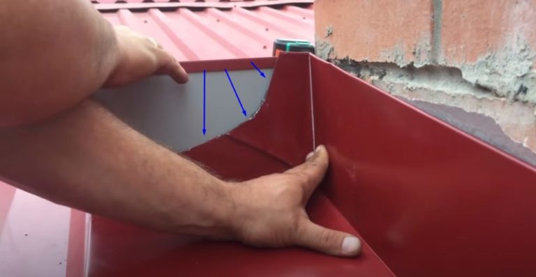
- Remove the temporarily attached counter flashing from the ridge side. Use metal shears to cut the pieces where you marked them. Reinstall the flashing. Roll the joints using pliers to bend the edges of the flashing.
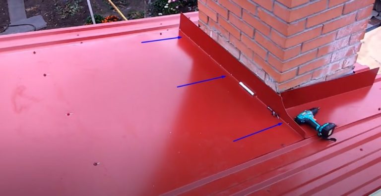
To prevent water from seeping under the counter flashing on the ridge side, lay a flat sheet of roofing metal on top of the bottom flange. Tuck the opposite end of the sheet under the ridge flashing or valley, depending on the roof configuration.
- On the eaves side, create the fourth counter strip similar to the extension piece attached to the opposite side of the pipe. The only difference is that you'll need to bend the blind corners on both edges, and bend the rolled edge over the cutouts on the side counter strips.
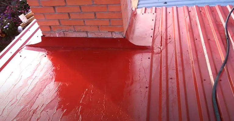
After installing the strike plates, check the ventilation passage for leaks. Use a hose to pour water from the top slope of the roof. The water should bypass the pipe and flow down the strike plates.
After successful testing, proceed to brickwork cladding. Cover the chimney with rolled metal to match the roofing color, and install the canopy.
The nuances of installing penetrations on different types of roofs
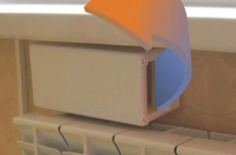
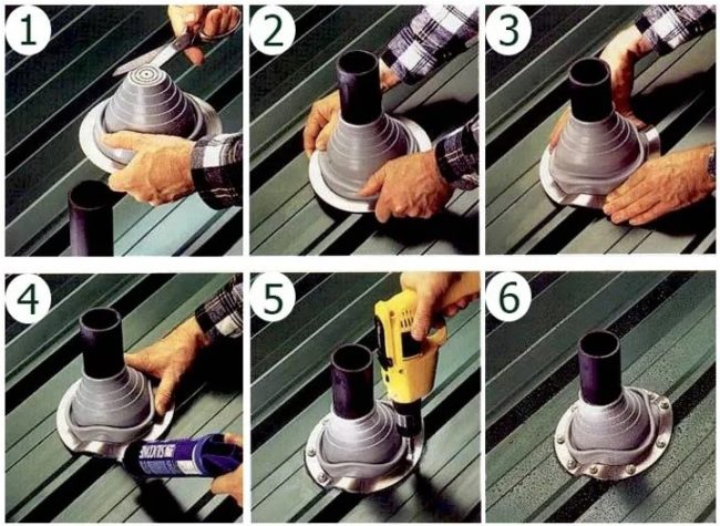
Place the penetration base on top of the seal. Screw the flange in place with self-tapping screws. While tightening, the mounting element with the seal is pressed firmly against the flat roofing surface. When screwing the flange to the corrugated sheet or metal roofing, the flexible side flanges conform to the wave shape of the roofing material.
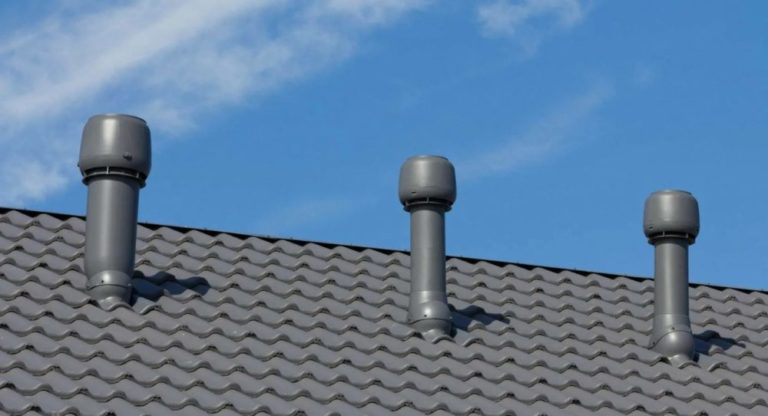
After installing the foundation, install the pipe with the deflector. From the attic side, connect it to the main building ventilation riser using a corrugated pipe.
Tape the edges of the cut thermal insulation and vapor barrier in the roofing pie passage to the air duct with tape.
Manufacturers produce ventilation penetrations tailored to roofing designs with specific duct diameters. Universal units are designed for installation on any type of roof.
The pass-through base is made of a pyramid-shaped rubber cap. By cutting off the desired portion of the elastic pyramid, you adjust the opening to the desired duct diameter.
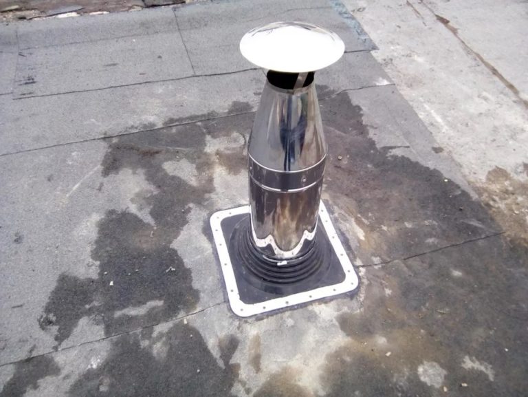
Sandwich pipes are often used to vent ventilation and chimneys to the outside. The duct is constructed with an internal channel. The space is created between the walls of the inner and outer pipes. The channel is filled with thermal insulation.
Insulation not only prevents condensation but also prevents the outer walls from being heated by exhaust gases from the boiler. The cold end of the chimney and ventilation duct made of sandwich pipe can be fitted with a universal, flexible, factory-made bushing.
The ventilation outlet on a roof with a concrete slab is installed using a factory-made round penetration. The openings are included during the building design stage.
To prevent the ventilation duct from coming into contact with the concrete, plastic bushings are used. These are inserted into the prepared openings. The joints of the duct leading outside are sealed by installing a protective cap.
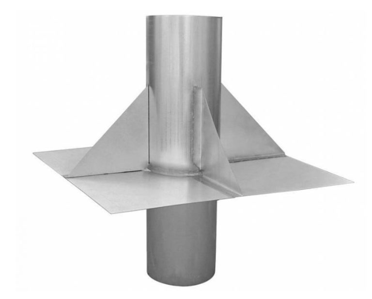
On a flat concrete roof, the ventilation outlet can be equipped with a round or square penetration installed on a reinforced concrete glass.
The metal feedthrough assembly features a wide mounting washer connected to the welded pipe by stiffening ribs called gussets. The pipe feedthrough support assembly is secured to the floor slab during the building's construction phase.
Recommendations for installation and operation of penetrations
Pass-through units are installed for ventilation and chimneys. The ventilation system exhausts air at a low temperature, which is safe for the roofing structure and the flexible base of the penetration.
The walls of a chimney made from a non-sandwich pipe can become hot from the high temperatures of the exhaust gases. Fire safety regulations require a non-combustible material belt between the chimney duct and the roofing structure. The chimney itself is often rectangular, and the penetration into the roof is created using flashings.
Recommendations for installation of penetrations:
- Install pipes vertically, without tilting. Bends, turns, and narrow sections impede airflow.
- Install a separate penetration for each exhaust duct. Avoid connecting ventilation risers with tees to the same duct as the penetration unit.
- For better draft, try to position the exhaust pipes closer to the roof ridge.
The main recommendation for operating and maintaining the penetration is to regularly inspect the unit at least once a year. Maintenance is most conveniently performed during the warmer months. Check the tightness of the flange screws against the roofing.
If you discover cracks, leaks, or hardware weakened by thermal expansion, remove and reinstall the unit, sealing the joints with sealant. Replace any damaged parts. To prevent roof leaks at the ventilation outlet, purchase original roof penetrations from the very beginning.
Answers to frequently asked questions
It is better to place ventilation closer to the ridge girder to improve draft.
A penetration is a shaped element that provides a sealed joint between the roof and the exhaust pipe leading to the street through a through hole in the roof.