To remove moisture vapor, metal roofing on a cold and insulated roof must be ventilated. Lack of air movement in the sub-roof space leads to condensation accumulation.
With each freeze-thaw cycle in winter, water tears apart the roofing cake, accelerating the destruction of the wooden elements of the rafter system.
We'll discuss the design, operation, and types of ventilation systems in more detail in this article. We'll also provide step-by-step instructions for installing roof ventilation for both insulated and cold roofs. Finally, we'll provide recommendations for maintaining your ventilation system and answers to common questions.
- Types of roof ventilation, purpose
- Continuous ventilation
- Spot ventilation
- Mixed ventilation
- Types of ventilation units and schemes, installation methods
- Cornice knot
- Turned Slope Knot
- Ridge knot
- Mechanical and natural ventilation scheme
- Roof ventilation system device, complete set
- Instructions for installing cold roof ventilation
- Instructions for installing ventilation for a warm roof
- Recommendations for ventilation maintenance
- Answers to current questions
- Video materials
Types of roof ventilation, purpose
The general purpose of roof ventilation is to ensure constant air circulation to remove moisture. Additional airflow reduces the heating temperature of the metal roofing tiles in the summer and protects the roof from freezing in the winter, reducing heat loss in the home.
To create unimpeded ventilation conditions, a continuous, point or mixed type of utility network is created, differing in the design of air flow removal from under the metal roofing tiles.
Continuous ventilation
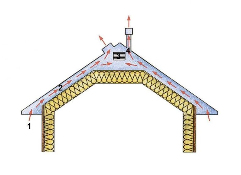
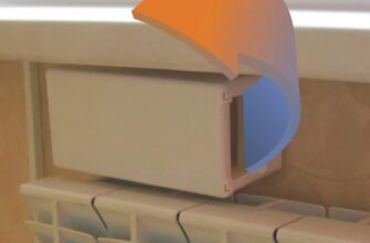
The system operates on the principle of free airflow in the space created between the metal roofing or corrugated sheeting and the roofing insulation. Airflow enters through vents in the eaves area. The outlet is located at the highest point of the roof. Exhaust vents are located in the ridge girder.
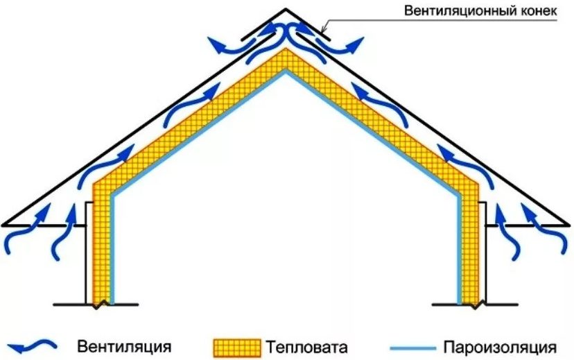
Continuous ventilation operates on the principle of natural stove draft and covers the entire roof area of a simple gable roof.
To create a sub-roof space between the tiles and the waterproofing membrane of the roofing cake, a gap of the size is created using a counter-batten made of timber minimum 50 mmAir vents are provided with a slit along the entire length of the slope or with holes. Grilles are installed to protect against contamination.
Design of continuous ventilation are engaged before the construction of the roof beginsCalculations determine the total size of the ventilation openings to be 1% of the total roof area. The system is installed during the roofing cake and tile or corrugated sheet installation.
Spot ventilation
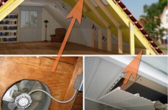
Complex roofs develop areas of stagnant air. This problem is typical for attics, roofs with multiple pitches, towers, and other architectural features. Air inflow typically originates from the eaves.
Freely flowing natural airflows do not capture exhaust air from the resulting pockets. To achieve exhaust in difficult areas, spot ventilation is installed using roof vents.
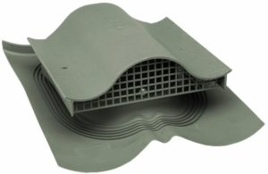
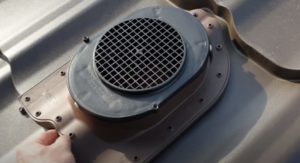
The design of the unit is made of a pipe with a deflector on top or a cap with a meshOne aerator is installed per sheet of metal roofing or corrugated sheeting. The pipe removes stagnant air from the sub-roof space.
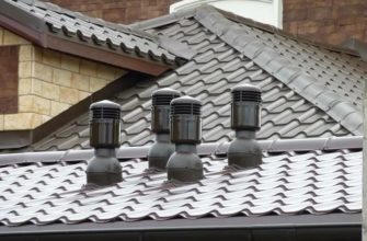
Problem areas arise on roofs with complex geometry and multiple ridge purlins. Point drainage aerators are installed along the perimeter of all ridge purlins, spaced at intervals of up to 600 mm.
Spot ventilation is not a one-size-fits-all solution. The system complements a continuous ventilation system. Installing aerators is also recommended on pitched roofs with a low slope.
Mixed ventilation
A mixed ventilation system combines continuous and spot ventilation. This option is suitable for attics and other complex roof shapes.
Air enters the sub-roof space through supply vents on the eaves. Exhaust air is removed through aerators and exhaust vents on the ridge caps.
Types of ventilation units and schemes, installation methods
The installation layout and design of ventilation units are determined based on the building's technical parameters. Sanitary standards and air exchange requirements are taken into account.
Ventilation is installed separately for the attic and under-roof space, or both. The type of roof—warm or cold—is taken into account.
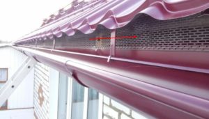
Cornice knot
On a roof made of metal tiles supply ventilation unit (continuous aerator) is made by a gap between the eaves and the last roofing sheet.
The gap to prevent debris and birds from entering is covered with a grate. The eaves under-roof ventilation unit is supplemented, if necessary, with an additional gap and grate for ventilation of the attic space.
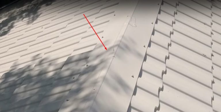
Turned Slope Knot
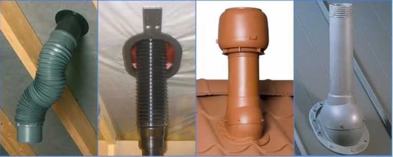
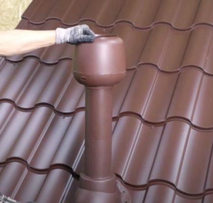
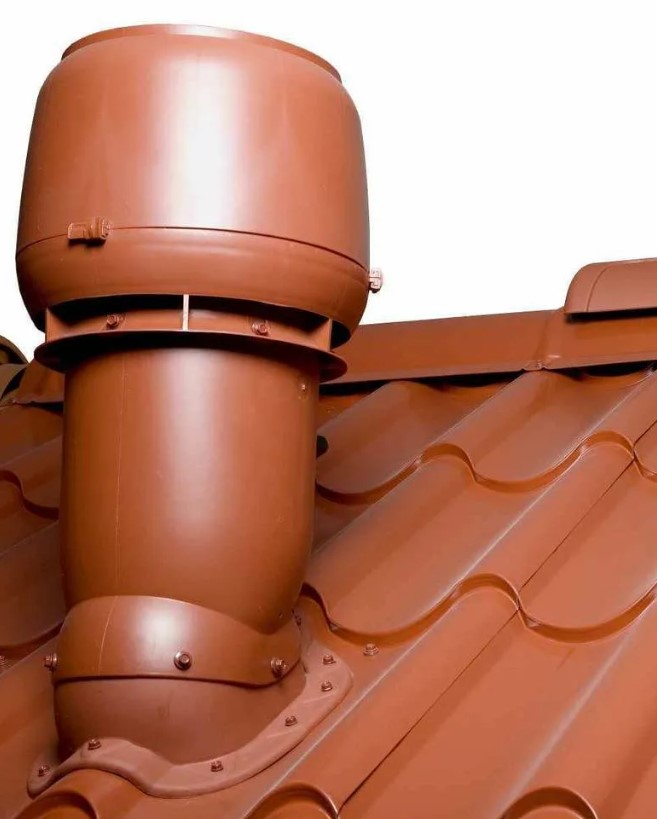
A roof slope vent allows air to freely exit from under the metal roofing tiles to the outside. A sealed passage is created through the roofing material into the under-roof gap. The slope assembly is designed to exit through a pipe with a deflector or a mushroom-shaped valve.
Advantage The first element is a lower probability of being covered with snow.
Flaw – the towering chimney slightly spoils the appearance of the roof.
Advantage of the second element - neat appearance. Low mold is practically invisible on the roof.
Flaw – high risk of snow blockage. Blocking the vent disrupts ventilation of the sub-roof space.
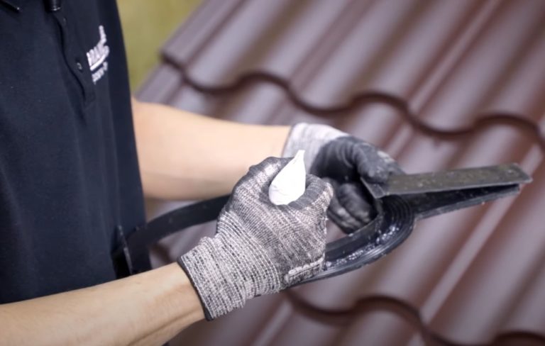
The pipe and cap are placed on the roof with a rubber sealing strip and secured to the metal roofing with screws. The joints are additionally sealed with sealant.
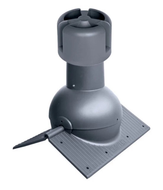
A point-type slope aerator for ventilation of a warm attic and connection of a common house exhaust system is a complete ventilation unit kit.
Pass-through element The flange is made from a pipe with a deflector. A penetration is cut into the through hole in the insulation layer. The flange is secured to the metal roofing with screws.
To seal the joint, a rubber seal is placed underneath. The joint is treated with sealant. To prevent condensation from the sub-roof space from entering the insulation, a water seal is installed. This part is made of a ring with two mating parts.
Once snapped into place, the teeth clamp onto the overhanging ends of the cut waterproofing membrane. The waterproofing ring is secured to the sheathing along its entire length with screws through perforated strips.
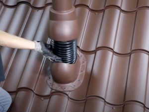
From the attic side, the ventilation ducts are connected to the protruding pipe using a corrugated sleeve. To improve draft in winter and prevent condensation, the pipes are insulated. Pass-through elements are installed separately for each ventilation riser.
Ridge knot
A point ridge vent is similar in design to a slope aerator, constructed from a pipe with a deflector. It differs in that its base is shaped like a ridge. The unit is placed on the ridge purlin and secured with screws.
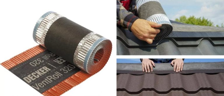
In addition to the point vent, a ventilation gap is created on the ridge purlin with a continuous vent along its entire length. To allow dirty air to freely escape from the sub-roof space while preventing birds and insects from entering, a ventilation strip is placed under the ridge purlin.
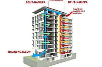
Mechanical and natural ventilation scheme
Natural supply and exhaust system – a commonly used roof ventilation method. Air circulation is achieved through draft created by the difference in air temperature and pressure.
Advantage – economic benefit. There are no electricity costs. There is no need to install fans or maintain equipment.
Flaw – dependence on natural factors. As draft weakens, ventilation of complex areas of the sub-roof space deteriorates.
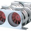
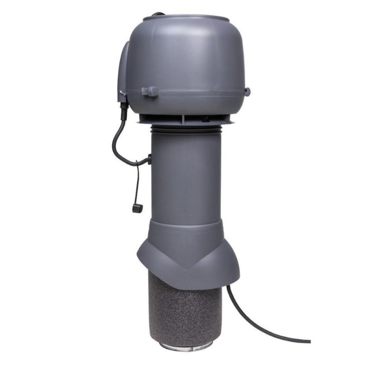
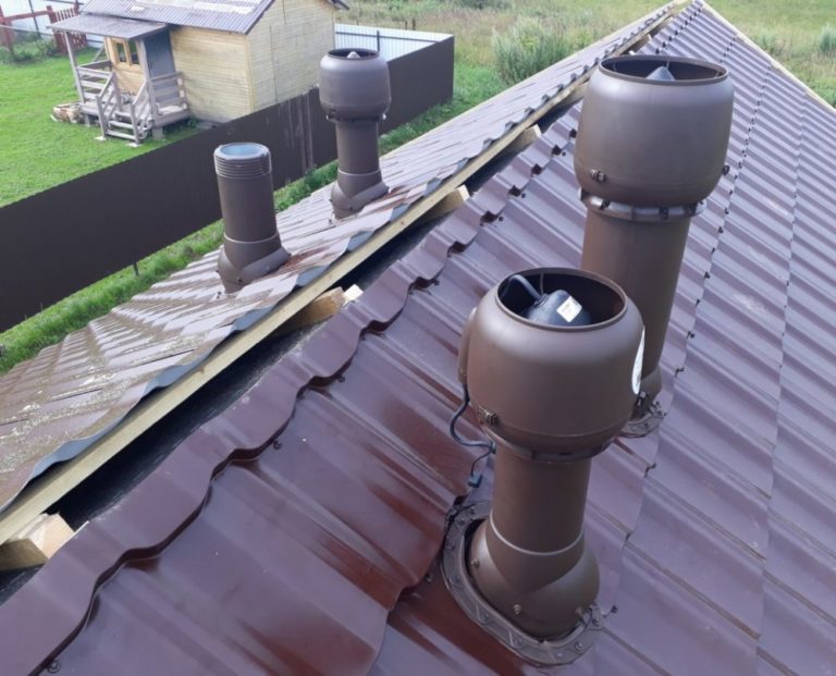
Mechanical supply and exhaust The system is ideal for large roofs with complex slopes. Turbine aerators are installed on the roof. The built-in fan is powered by an electric motor. Rotating blades ensure consistent air extraction from under the roof.
Advantage – independent of weather conditions. The hood operates as long as the fan is running. Air is supplied naturally through continuous or spot aerators.
Flaw – energy consumption, need for equipment maintenance.
Roof ventilation system device, complete set
The ventilation system and its components are individually determined based on the technical parameters of the roof. Continuous aerators are installed along the entire length of the eaves and ridge purlin. The number of point vents is determined by calculation. The following rules are followed:
- To ensure air flow, a continuous eaves aerator is fitted with a 20-25 mm wide, closed-grate slit. Intermittent air inlets are also permitted. The diameter is determined by the slope of the roof: up to 15O – 25 mm, more than 15O – 10 mm. Total area of the inlet openings – 200 mm2/1 m of cornice length.
- To ventilate the under-roof space, the gap between the metal tiles and the roofing cake is maintained at 50 mm.
- Point ridge and slope vents are installed to exhaust air. Continuous aerators are installed under the ridge flashings. Regardless of the type of exhaust units installed, the area of all openings should be 10-15% larger than the total inlet area.
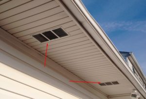
- Separate vents are installed for attic ventilation. The total area of the vents should be 0.02–0.03% of the attic floor area.
- The maximum distance from the ridge for installing a point slope aerator is 600 mm. The recommended distance is 150 mm.
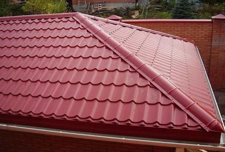
On a gable roof Continuous ventilation is usually sufficient. For complex roofs, a mixed system with the addition of point aerators is installed.
A hip roof made of metal tiles has triangular slopes at both ends instead of gables. The ventilation system can be continuous, like a gable roof, but with some modifications:
- Air movement from the inlet eaves gaps to the exhaust ridge gaps is ensured along the ridge.
- When installing continuous sheathing, a break is created in the counter sheathing at the ridge. Through this gap, supply air enters from the sub-roof space of the end slope and is directed to the ridge vent.
The second design is suitable for hipped roofs with soft roofing. Solid sheathing is not used under metal tiles and corrugated sheets. Continuous air flow is directed along the ridge.
Instructions for installing cold roof ventilation
Example of ventilation installation instructions for a cold gable roof:
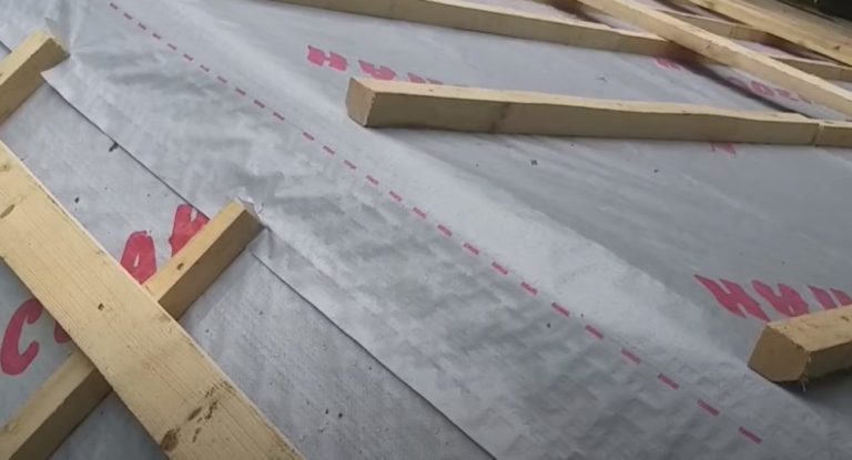
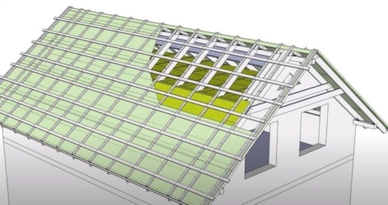
- To create a ventilated under-roof space, lay a waterproofing membrane on the rafters. Attach 50 mm thick counter battens on top. These will serve as a base for securing the sheathing boards for the metal roofing installation.
Counter battens will create a gap between the waterproofing and the roofing sheets. Lay the sheathing boards on the battens along the entire slope, except for one row near the ridge to facilitate installing an air vent.
- Lay the membrane on both slopes, offset from the ridge purlin to create a 100 mm gap along the ridge. You can lay the waterproofing flush with the ridge purlin. After securing it with a counter-batten, cut a strip of membrane along the ridge purlin with a knife.
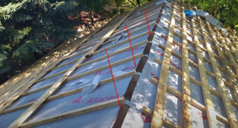
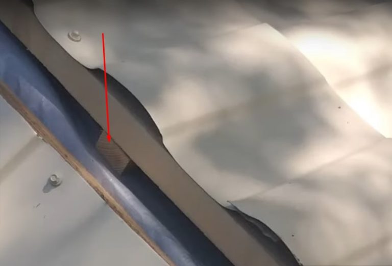
- In the gap area, create a continuous air valve along the length of the ridge. Cut a 40-50 cm wide strip of membrane so that the edges overhang the ridge purlin by 20-25 cm on both slopes. To secure the air valve strip, make 25 cm deep cuts in the center of the counter battens.
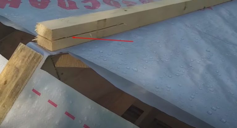
- Cover the gap left on the ridge purlin with a strip of membrane. Insert the edges of the membrane into the cuts in the counter battens.
- A gap is created between the main membrane and the strip attached to the ridge. The resulting air valve will allow stale air and moisture vapor to escape from the cold attic.
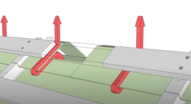
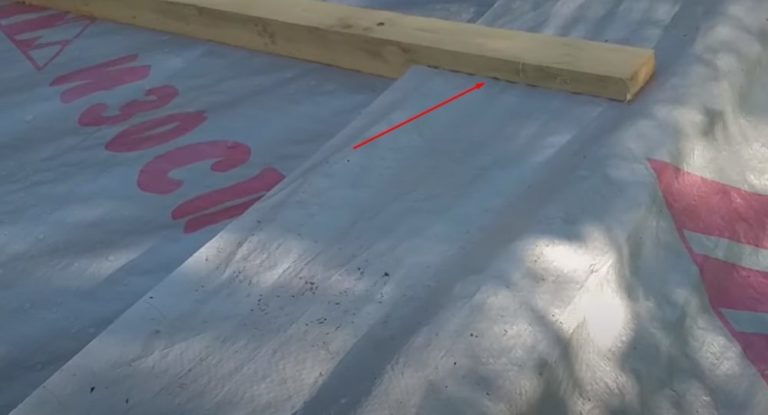
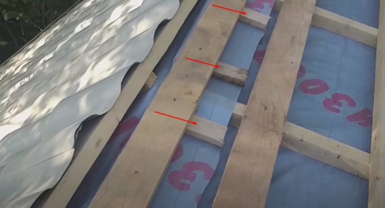
- Lay the last row of sheathing along the ridge. To ensure that air escaping from the attic and sub-roof space is exhausted through the continuous ridge vent, create ventilation gaps.
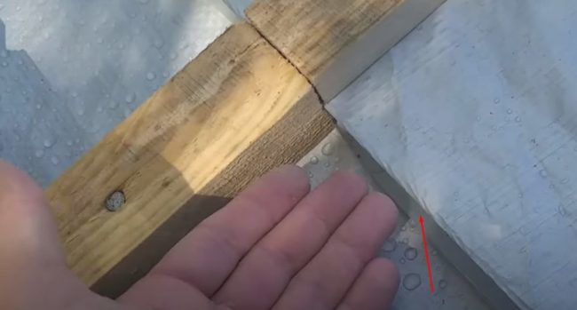
Place bars under the edges of the air valve strip on both sides of the slope: one 50 mm thick in the center between the rafter legs or two 25 mm thick on each side of the rafter.
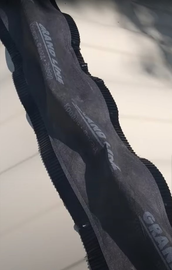
- Cover the slopes with metal roofing tiles. Leave a 10 cm gap along the ridge purlin for a continuous aerator.
- Place the ridge aerator tape over the gap.
- Install the ridge cap. Secure the trim pieces to the top sheathing board with screws.
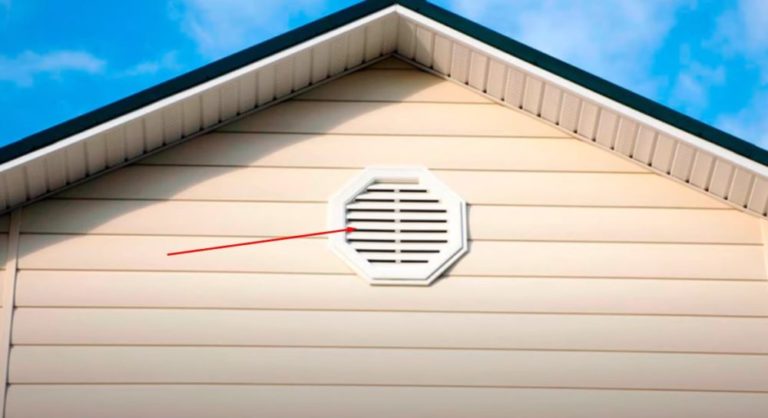
Equip both gables with dormer windows for ventilation and airing of the attic space in the summer.
Instructions for installing ventilation for a warm roof
The main under-roof ventilation for an insulated roof operates and is installed in the same way as for a cold roof. The only difference is the presence of a thermal insulation layer. On the attic side, the layers are laid in the following order: vapor barrier, mineral wool, and membrane.
Counter battens, sheathing boards, and metal roofing tiles are attached to the membrane. The attic is ventilated through dormers. Air movement in the sub-roof space flows from the eaves to the ridge.
In complex areas, additional ventilation outlets are installed using pass-through elements. Let's look at detailed instructions for installing a pass-through with a pipe for connecting a general-purpose ventilation riser:
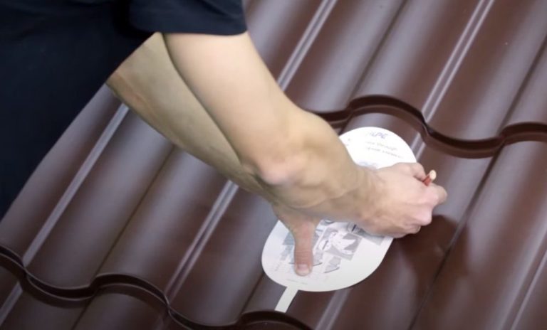
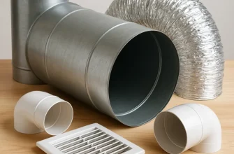
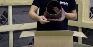
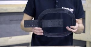
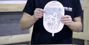
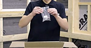
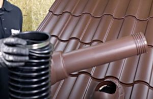
- Create a ventilation passage through the roof using shaped elements produced by the metal roofing manufacturer. The flange shape is guaranteed to fit the curves of the roof. The kit includes: a passage element, a water seal, a template with installation instructions, a non-acetic sealant, fasteners, a ventilation outlet pipe with a corrugated sleeve, and a deflector.
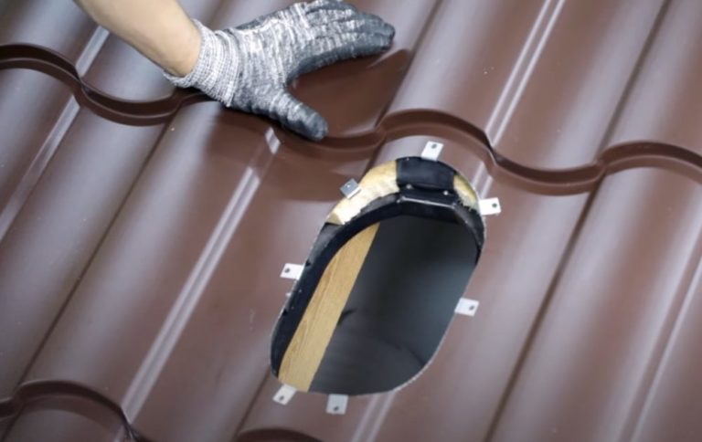
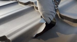
- Determine the installation location of the penetration, ensuring the hole does not fall on the rafter. Place the template, tab down, on the metal roofing. Trace the outline with a marker.
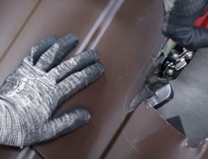
- Step back 2-3 cm from the marking line. Drill a hole with a 10-12 mm drill bit. Use metal shears to cut out the metal tile along the marking line. Start cutting from the drilled hole.
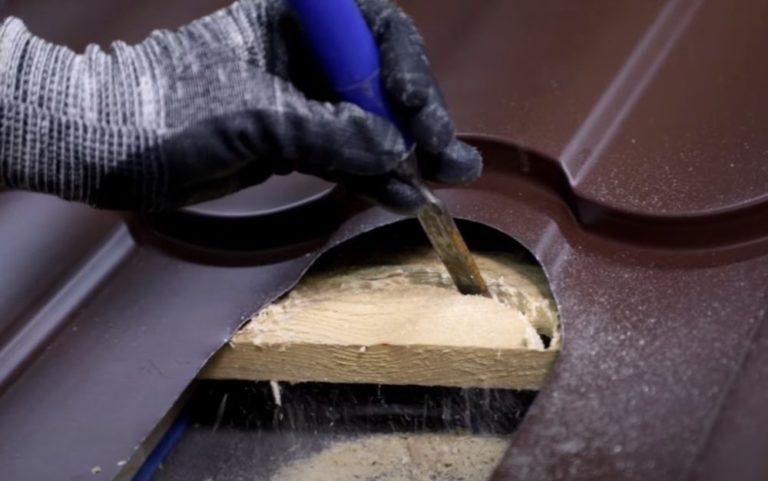
- The cut hole for the penetration may overlap the edge of the sheathing board. Remove the interfering piece of wood with a chisel. To make cutting easier, drill a row of holes along the outline of the piece.
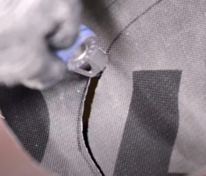
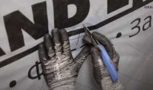
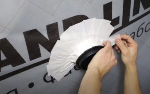
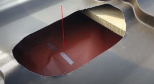
- To install the water seal, insert a rubber fitting into the cut hole. Use a marker to mark the inner contour of the ring on the waterproofing membrane.
- Using a knife, cut out a section of the membrane along the markings. Lubricate the flange of the water seal ring with a non-acetic sealant.
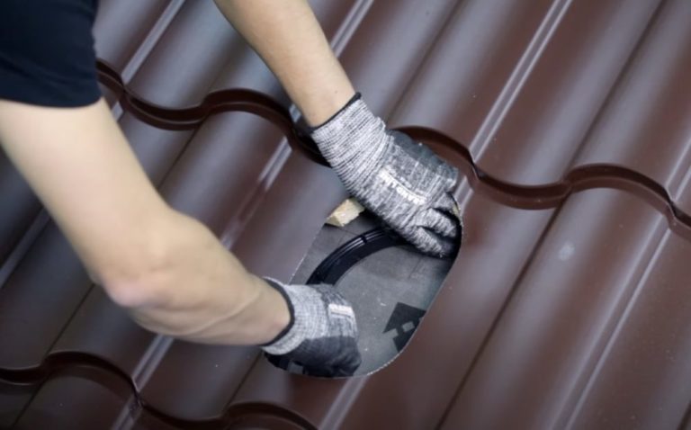
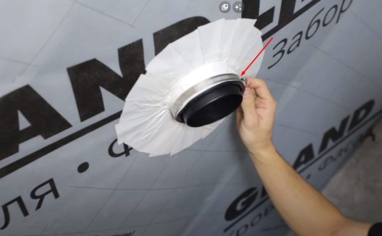
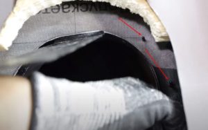
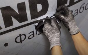
- Insert the water seal ring through the cut hole under the waterproofing membrane. Glue it to the membrane with the flange. Place the edges of the waterproofing membrane onto the tenons located around the perimeter of the ring.
- Place the tongues of the water seal under the metal roofing tiles, place them on the lathing board, and secure with screws.
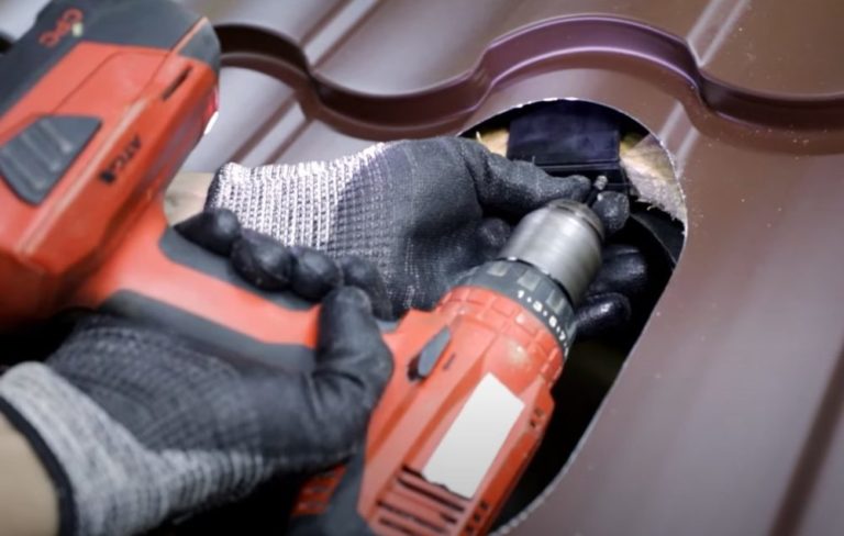
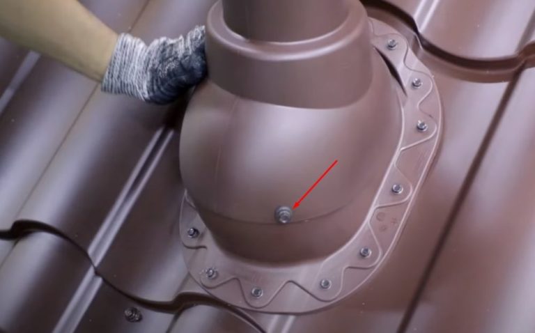
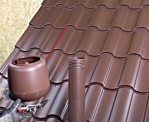
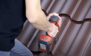
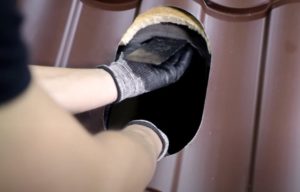
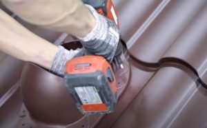
- Install the penetration piece over the opening in the metal roofing tile. There are perforations around the perimeter of the flange for fasteners. Use the drilling template to drill the holes in the metal roofing tile for the screws. Once completed, remove the penetration piece.
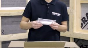
- Install the reinforcing plates included with the fasteners onto each drilled hole. These metal elements will prevent the screws from rotating in the thin metal roofing material and ensure a secure joint.
- Apply sealant around the perimeter of the penetration flange. Install the fitting onto the metal roofing tile and secure with screws. Connect the water seal ring from the inside to the penetration base.
- Take the ventilation outlet pipe and connect the lower part to the corrugated pipe. Secure the joint with a clamp.
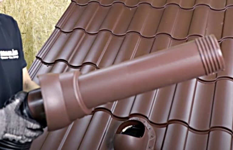
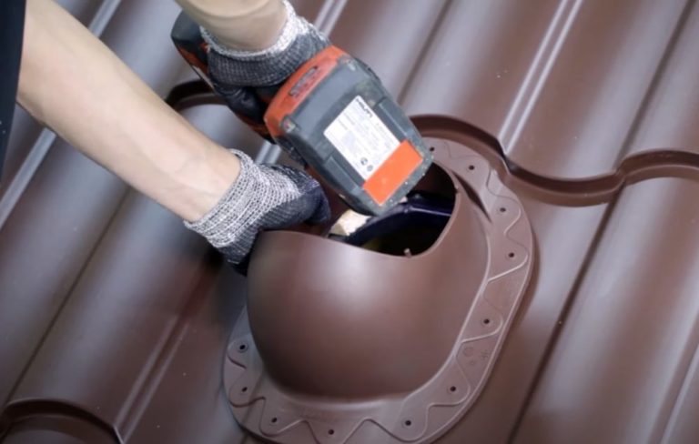
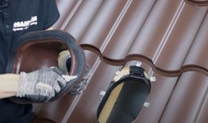
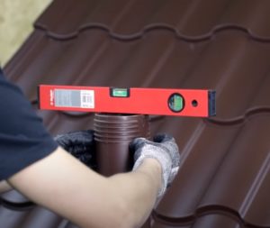
- Install the pipe with the branch pipe into the penetration. Align the ventilation outlet with a level.
- Fix the pipe to the base of the pass-through element with self-tapping screws.
- Mark the location of the corrugated pipe on the vapor barrier on the attic side. Cut the film with a knife.
- Make cuts along the edge of the vapor barrier around the perimeter of the hole using petals. Draw out the edge of the corrugated pipe. Press the petals of the vapor barrier against the wall of the corrugated pipe and secure with adhesive tape.
- Place a clamp on the end of the corrugated pipe. The outlet on the attic side is now ready for connection to the ventilation riser. After connecting the air duct to the corrugated pipe, tighten the clamp.
- Install a deflector on the pipe from the street side.
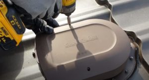
Install the roof vent using the same principle, but without cutting the waterproofing. The aerator will remove air from the sub-roof space of the roof slope. A step-by-step installation guide for the roof vent is shown in the photo.
Recommendations for ventilation maintenance
- To ensure proper ventilation, cover the vents with grilles to prevent birds and large debris from entering.
- Clean from dirt at least once a year.
- Install penetrations with insulated pipes to prevent the formation of condensation and ice.
- For a roof longer than 10 m, the eaves and ridge ventilation gaps are not sufficient.
- Additionally, install spot aerators to relieve the load.
Answers to current questions
Metal roofing produces significant condensation. Unventilated, accumulated moisture will damage the insulation and rafters.
Leave gaps along the length of the eaves and ridge. Install roof vents 15-60 cm from the ridge purlin. For attic ventilation, install dormers on the gable ends of a gable roof.
A cold roof has no thermal insulation layer. The tiles are laid on a sheathing with a waterproofing membrane underneath.
The membrane is part of the structural unit that creates a ventilated space in the sub-roof space. The film prevents condensation from penetrating the rafters and into the attic space.