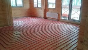
Underfloor heating is gaining popularity these days, offering a sense of comfort. However, for this type of heating to function effectively, a pump-mixing unit is required. It allows for the optimal temperature of the coolant to be maintained and its flow to the heating loops to be regulated.
Therefore, we decided to discuss existing pump-mixing units and their components. You'll learn how to assemble a mixing unit for underfloor heating yourself, as well as installation and setup.
- Functions
- Operating principle
- Application areas
- Types
- Schemes of pumping and mixing units
- With series connection of the pump
- With parallel
- Which mixer is better to choose?
- Equipment
- Pump
- Flow regulator
- Bypass valve
- Auxiliary elements
- Collector block
- Making a mixing unit with your own hands
- Installation of a mixing unit
- How to set up
Functions
Using a thermal mixing unit when installing underfloor heating allows you to create an independent water heating system with the ability to regulate the coolant temperature.
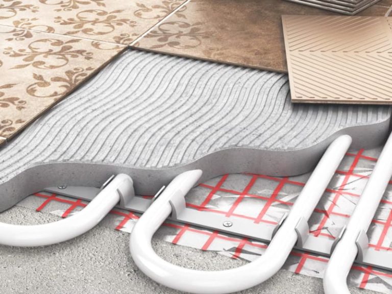
Hydronic underfloor heating is a low-temperature system. Water supplied to the underfloor piping should be no hotter than 55°C. Since this system is often connected to a radiator or boiler, where the water temperature is much higher, a special mixing module is required.
It is in this unit that the cooled coolant from the return line is mixed with the hot water coming from the heating source to the required level.
This water mixing device also controls the volume of coolant flowing into each loop.
Operating principle
The basic operation of any pump-mixing device is the same. The heated coolant, moving from the source, passes through a thermostat, where its temperature is recorded. The water then enters the safety valve, where its temperature is regulated by opening and closing the valve head.
If the coolant temperature exceeds a preset value, the safety valve opens and cooled water from the return line is added. When the desired temperature is reached, the supply is shut off.
A pump is responsible for the circulation of liquid in the hydraulic unit; the uniformity of heating of the floor surface depends on its operation.
Application areas
The need for a pump-mixing unit arises when water is the coolant. Let's find out in what cases this occurs.
- If the water-heated floor is connected to the central heating system, this is because the water temperature in the centralized system exceeds the required level for underfloor heating.
- When connecting from a boiler that does not operate with a return of +55 and below - these are all solid fuel boilers and those operating on gas.
- If the main line has two or more circuits with different temperatures (warm floors with radiators).
Types
All pumping and mixing units are divided according to the type of working element:
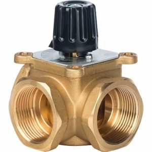
- With a three-way valve — are installed in large rooms, as the unit can handle a large volume of water. This mixing tee is usually connected to an external temperature sensor, allowing the heating level to be adjusted based on the outside temperature. Regulation is accomplished using a damper located at the junction of the supply and return pipes. A sequential design is typically used.
- With two-way — Recommended for rooms up to 200 m², it can be connected in both parallel and series mixing configurations. The valve has a thermostatic head with a sensor that monitors the temperature and shuts off the hot water supply when the temperature exceeds this level. The volume of liquid this design can handle is small, so the adjustment process is smooth.
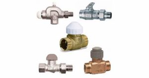
- Combined — combine a valve and a balancing unit. However, this option is rarely used with heated floors.
Schemes of pumping and mixing units
Pump-mixing units are assembled in several ways, the difference lies in the pump connection and the valve design.
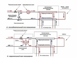
With series connection of the pump
When the pump is turned on, the sequential circuit only prepares the coolant and ensures its movement through the loops. Despite the need for two separate devices to pump fluid through the primary and secondary circuits, this circuit is technologically more advanced.
It offers higher performance than a parallel connection. Therefore, professionals often use this option when installing underfloor heating.
However, for the floor to work effectively in this type of installation, the correct calculation and adjustment, as well as the accuracy of the drawing, play an important role.
With parallel
The advantage of a parallel system is that only one device is required to pump water through both circuits. This significantly simplifies the installation process, but a more powerful unit is required.
If the mixing unit is being designed for a small heating system, a parallel layout is recommended. Since DIY assembly of this design is less likely to cause problems, it's easier to avoid serious errors. However, this design is unsuitable for larger underfloor heating systems due to its low performance and efficiency.
Which mixer is better to choose?
When selecting a thermostatic mixer, it's important to consider the characteristics of the heating device. When selecting distribution equipment, consider the mixing method—central or lateral.
If the area is large, with several separate circuits, a mixing unit with a three-way valve is essential. This unit handles large volumes of liquid perfectly. For a single-circuit floor, a manifold with a two-way mixer is suitable.
You can make a pump-mixing unit for underfloor heating yourself, but if you're buying a ready-made one, we recommend these models:
- VT.COMBI and VT.COMBI.S are designed for preparing low-temperature coolant. A two-way valve is used, controlled by a thermostatic head or servo drive. A temperature sensor is not included and must be purchased separately.
- VT.COMBI — the unit is equipped with a balancing valve, which is used to regulate the pressure in the system.
- VT.COMBI.S — this model of the NSU manifold can be connected to both the inlet and outlet. Therefore, it can be used with both radiator and TP heating systems.
- VT.DUAL — the mechanism consists of two modules (pump and thermostat), with a manifold assembly located between them. Mixing is accomplished by a three-way valve with a thermostatic head.
These are proven models and it is better to buy them.
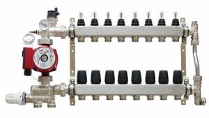
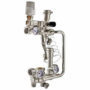
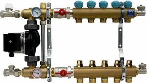
Equipment
The mixing unit is a complex mechanism responsible for maintaining a stable water temperature and ensuring its continuous circulation. It is part of the manifold block and consists of a number of mechanisms.
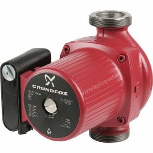
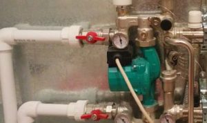
Pump
The pump's primary function is to create a constant flow of water through the pipeline. It delivers and returns water through the manifold and floor drains. Its key performance indicators are pressure and flow rate.
When properly sized, the pump will overcome the hydraulic resistance in the floor line. It is recommended to use a device with an automatic mode selector.
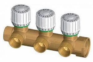
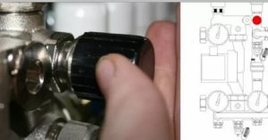
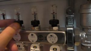
Flow regulator
Flow meters are:
- The primary circuit balancing valve (float valve) controls the amount of coolant entering the main line from the primary high-temperature source. The flow is regulated by its capacity. Adjustment is made by a valve with a head, which is turned by a key. Adjustment is also made by a thermostat valve, controlled by a remote sensor.
- The secondary circuit balancing valve is adjusted based on the size of the area being heated. Opening and closing the control valve changes the proportions of heated and cooled flows. Closing the secondary circuit return balancing valve increases the flow of hot coolant from the boiler, which increases thermal conductivity.
The opening degree is adjusted using a scale marked on the flask. This scale determines the device's flow rate in cubic meters per hour.
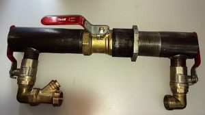
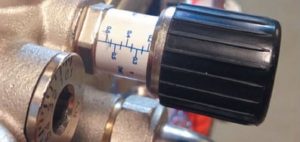
Bypass valve
A bypass, coupled with a bypass valve, ensures uninterrupted operation of the pumping equipment when back-up mode is active—when fluid circulation in the floor pipe is completely or partially interrupted. This can occur if the loop valves on the manifold are closed manually or using valves.
As a result, resistance to water flow increases, as does the load on the mechanism. The pressure in the system increases, and the bypass valve opens.
The coolant flows through the bypass pipes and pump, thereby closing the small circulation loop. This eliminates emergency situations.
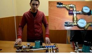
Auxiliary elements
Auxiliary elements are also responsible for monitoring and maintaining the efficient operation of the pump-mixing system. These include:
- thermometer - controls the temperature of the coolant;
- air vent - through it air is removed from the system;
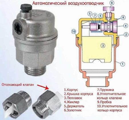
- drainage taps, their purpose is to drain water;
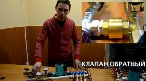
- Check ball valve - prevents the coolant from moving in the opposite direction.
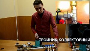
Collector block
The manifold group is where the underfloor heating circuits are connected and is designed for a specific number of branches. It includes a supply and return comb.
Making a mixing unit with your own hands
When installing underfloor heating, you can choose a ready-made pump-mixing unit. However, if you're looking to build a budget-friendly unit yourself, we'll walk you through the step-by-step process.
Before you start working, you need to stock up on: a mesh filter, three-way thermostatic A check valve, two thermometers, a circulation pump, an air vent, two tees, two drain valves, and ball valves. Manifolds are also included—one for the supply line with ball valves and one for the return line with regulators.
In addition, the number of loops of the warm water floor must be equal to the outlets on the manifold.
Step-by-step assembly instructions:
- We install a mesh filter to the ball supply valve, after which we install a corner.

- We screw a three-way thermostatic mixing valve to the corner.

- We screw a check valve to the mixer, on the side where the return line will be connected - without it, the unit will not work correctly.
- We install thermometers on the return line and on the middle outlet of the mixing unit.

- We connect the circulation pump to the thermometer running from the supply pipe. The straight distance from the thermometer to the pump and from the pump to the manifold must be equal, equal to 10 times the diameter of the supply pipe.

- Next we install the collectors, which are secured to a special bracket. We connect a supply manifold with ball valves to the pump, and the return manifold will have control valves.

- We screw tees to the end outlet of the supply and return manifolds, to which the air vent is attached.
- We install an air vent.
- We install drain ball valves on the side outlets of both tees. These are necessary for filling and draining the system.

- Connect a section of polypropylene or metal-plastic pipe to the return manifold. Its length should be equal to the distance from the supply manifold to the thermometer.

- Between this section of pipe and the return thermometer we place the second mesh filter.

- We screw a ball valve to the check valve.
The result is a simple, inexpensive model of a homemade pump-mixing unit for underfloor heating.

Installation of a mixing unit
Before installing the distribution unit, you need to determine its location. It can be installed in the room where the floor will be installed or in the boiler room of a private home.
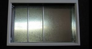
The unit can be mounted directly to the wall or in a metal cabinet built into a recessed wall. It is equipped with adjustable guides and doors. A manifold housed in such a cabinet looks aesthetically pleasing, but it is not cheap. It is important that all electrical appliances are grounded and that the unit is easily accessible.
The mixer should be mounted at the highest point of the system; this will make it easier for air to escape from it.
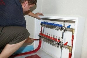
The pumping and mixing unit is installed in the following sequence:
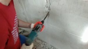
- A niche is prepared in which the manifold cabinet is placed.
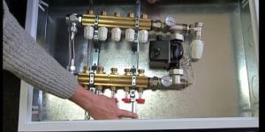
- The mixing and distribution unit is installed in the cabinet.
- The corresponding pipes from the boiler are connected to the ball valves of the manifold.
- The floor contour pipelines are screwed to the comb outlets.
The hydronic underfloor heating system is now installed, and its quality can be checked for leaks. Only then can the screed be poured and the finishing material laid.
How to set up
After installing the heated floor and connecting it to the installed manifold, the system must be configured to ensure comfortable conditions in the apartment.
Adjustment of the pump-mixing device:
- We remove the thermostat, it can affect the regulation process.
- We set the bypass valve to the maximum level so that it does not operate during adjustment.
- Let's begin adjusting the balancing valve. The water temperature is based on the following parameters: boiler outlet (+95°C), floor inlet (maximum +45°C), and outlet (maximum +35°C). The acceptable temperature difference between the supply and return water is 5-10°C, no more. Using the formula, you can perform simple calculations:
T1 - 95 - 35 = 60
T2 - 45 - 35 = 10
K - ((60 : 10) - 1) x 0.9 = 4
This indicator is set on the balancing valve.
- We now proceed to adjusting the pump. It is set to minimum power and gradually increased until the required pressure level is reached.
- We adjust the bypass valve. It is set to a value 10% higher than the maximum operating pressure.
If the heated floor has several circuits, it is necessary to adjust each loop in this way.
The pump-mixing unit is the "heart" of hydronic underfloor heating systems; without it, they won't operate efficiently or deliver full heat output. Therefore, when installing underfloor heating with multiple circuits, this mechanism is mandatory. Whether to purchase it or assemble it yourself is up to you.